Flashing) | .. Set up image aliases for inline use.
3. A Tour of RAD-Comet2 Hardware
3.1. Label and Status Indicators
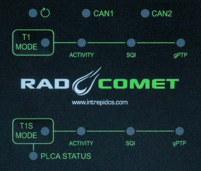
3.1.1. Device status 
The device status is indicated on the top left of the membrane with this LED, .
The following table describes the LED behavior based on device state.
|
Device Powered |
|
Host Computer Connected |
|
Device online with host computer |
|
Coremini active |
 (Flashing)
 (Flashing)
 (Alternating)
 (Flashing)
3.1.2. CAN1/2 Status
|
Message TX |
|
Message RX |
|
Network Error |
 (Flashing)
3.1.3. PHY Mode
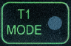
The mode each PHY is displayed by the status LED within the corresponding membrane button.
Switching LED status between T1S ports
RAD-Comet2 has 2x T1S ports but only 1 set of status LEDs. The color of the LED indicates which T1S port’s status is displayed as listed below. Briefly pressing the “T1S MODE” button toggles between which port’s status is displayed by the LEDs.
PHY Mode |
Link Speed |
||||
AE1 |
|
|
Slow Flash: Link Down Fast Flash: 100 Mbps Solid: 1 Gbps |
||
|
|||||
|
|||||
AE2 |
AE3 |
||||
AE2/AE3 |
|
CSMA/CD Mode |
|
|
Always 10Mbps |
PLCA Coordinator |
|
|
|||
PLCA Follower Node |
|
|
|||
 = Auto (Link Down)
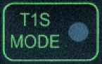

Changing between coordinator and follower node
The RAD-Comet can be toggled between coordinator and follower by holding “T1S MODE” for 3 seconds. The node ID of the follower is configured using neoVI Explorer.
3.1.4. Link Activity
|
Frame TX |
|
Frame RX |
|
Error |
3.1.5. Signal Quality Index (SQI)
SQI is a 3-bit value reported by the PHY that correlates with the BER (Bit Error Ratio) of the link communication. The behavior of the SQI LED is shown below.
|
SQI = 0 |
BER > 10e-10 |
SQI = 1 |
||
SQI = 2 |
||
|
SQI = 3 |
BER < 10e-10 |
SQI = 4 |
||
|
SQI = 5 |
|
SQI = 6 |
||
SQI = 7 |
3.1.6. gPTP
This LED displays the gPTP configuration of AE1
|
Disabled |
|
Leader |
|
Follower |

3.1.7. PLCA Status
The PLCA status is reported by the 10BASE-T1S PHY and displayed below the T1S Mode button according to the following table.
|
Beacon Present |
|
Collision |
|
Jabber Detected |
|
Unexpected Beacon |
|
Empty Cycle |
|
RX in Transmit Opp |
Note:
The settings described in this section can also be modified using neoVI Explorer or libicsneo, Intrepid’s open source cross-platform device communication API.
3.2. Bootloader Mode
You may see all the LEDs on the top label flashing synchronously. This means the device is in bootloader mode, which should only happen when flashing the device’s firmware. If this is observed unexpectedly or following a firmware update, please contact customer support for assistance.
3.3. Connector Interfaces
3.3.1. Power/USB/1000BASE-T Interfaces
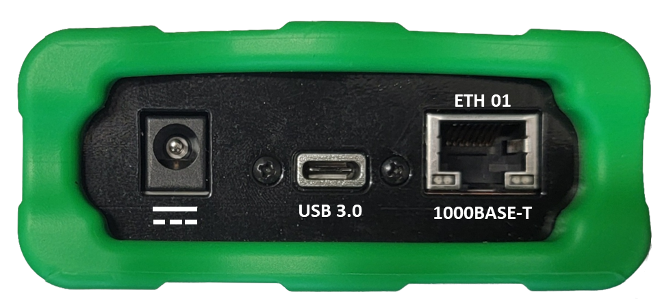
Barrel Jack (Left):
The device can be powered using a DC supply between 5.5-40V volts with a minimum power of 10 Watts. Using a power supply that does not meet these requirements may cause the device to malfunction or be permanently damaged.
USB Type C (Center):
This serves as a connection to a host computer for configuration, firmware updates, and PHY register access.
USB Power
RAD-Comet2 cannot be powered via USB
ETH 01 (Right)
The industry standard RJ-45 Ethernet jack is a 10/100/1000BASE-T port that can be used to connect to a host computer or be used as a network port for sending and receiving Ethernet traffic.
Link LED (Green): Indicates that a valid link has been established between your device and another 10/100/1000 Ethernet device.
Activity LED (Orange): Flashes when traffic passes in either direction over the attached Ethernet cable.
In normal operation you should see the Link LED always on, and the Activity LED flashing at a variable rate, with faster flashing meaning that more data is being transferred.
3.3.2. Ethernet Interfaces
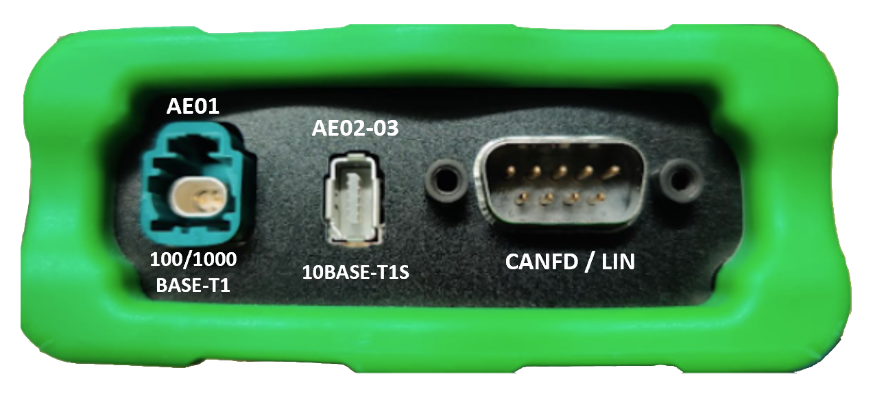
AE01
The H-MTD connector on the left is a 100/1000BASE-T1 port with the following following pin assignments.
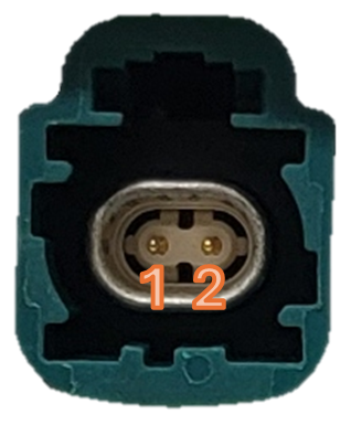
H-MTD Connector Pinout |
||
Pin # |
Label |
Description |
1 |
TRD+ |
Data transmit and receive, positive |
2 |
TRD- |
Data transmit and receive, negative |
AE02 - AE03
The IX connector in the middle contains two 10BASE-T1S Ports with the following pin assignments. Note that each port has twisted pair designated “IN” and a twisted pair designated “OUT”. The redundant signals are tied together electrically inside the device and can be useful to minimize stub length by inserting the RAD-Comet2 into a mixing segment such that the connection a daisy-chain “IN” and “OUT” of the RAD-Comet2.
Pin |
Signal |
Cable Color |
1 |
AE_02_IN_P |
white/orange |
2 |
AE_02_IN_N |
orange |
3 |
GND |
– |
4 |
AE_02_OUT_P |
blue |
5 |
AE_02_OUT_N |
white/blue |
6 |
AE_03_IN_P |
white/green |
7 |
AE_03_IN_N |
green |
8 |
GND |
– |
9 |
AE_03_OUT_P |
white/brown |
10 |
AE_03_OUT_N |
brown |
3.3.3. DB-9 Connector
The DB-9 connector on the right holds two CAN FD channels, 1 LIN Channel, and can also be used to power the RAD-Comet2. Pin assignments are listed in the table below. See this section for detail on power supply requirements.
Pin |
Signal |
|---|---|
1 |
LIN (Must use isolated GND) |
2 |
CAN 1 L |
3 |
Isolated GND |
4 |
CAN 2 L |
5 |
GND |
6 |
Isolated GND |
7 |
CAN 1 H |
8 |
CAN 2 H |
9 |
VBATT |