3. A Tour of RAD-Comet3 Hardware
3.1. Label and Status Indicators
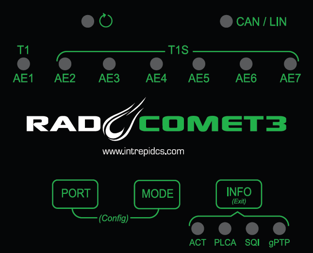
3.1.1. Device status 
The device status is indicated on the top left of the membrane with this LED, .
The following table describes the LED behavior based on device state.
|
Device Powered |
|
Host Computer Connected |
|
Device online with host computer |
|
Coremini active |
 (Flashing)
 (Flashing)
 (Flashing)
3.1.2. CAN/LIN status
|
Message TX |
|
Message RX |
|
Network Error |
3.1.3. Ethernet Port Status Information (Comet3)
The statuses of Ethernet Ports 1-7 are displayed in the row of tri-colored LED’s at the top of the
label. The information displayed has 4 different contexts with the active context indicated by
the row of green LEDs in the bottom right of the label. The context can be changed by pressing 
Active Context |
LED Behavior |
Port Status |
(Activity) |
|
Frame Transmitted |
|
Frame Received |
|
|
Error (e.g. Bad CRC, PLCA error) |
|
|
|
BEACON present |
|
Collision |
|
|
Jabber |
|
|
Unexpected BEACON |
|
|
Empty Cycle |
|
|
CSMA/CD Mode |
|
|
|
See chart below |
|
|
Disabled |
|
Leader |
|
|
Follower/Locked |
|
|
Follower/Not Locked |
|
|
Error |


Signal Quality Index (SQI)
SQI is a value reported by the PHY that correlates with the BER (Bit Error Ratio) of the link communication. 10BASE-T1S is a 3-state value and BASE-T1 is a 3-bit value. The behavior of the SQI LED is shown below.
LED Color |
SQI |
Bit Error Ratio |
|
T1S |
T1 |
||
|
0 |
0 |
BER > 10e-10 |
1 |
|||
2 |
|||
|
1 |
3 |
BER < 10e-10 |
4 |
|||
|
2 |
5 |
|
6 |
|||
7 |
|||
3.1.4. Ethernet Port Mode Display
Holding  will display the port configuration of each port until it is released.
Reference the following tables for how the speed and mode are represented
for the BASE-T1 ports and PLCA configuration is represented for T1S ports.
will display the port configuration of each port until it is released.
Reference the following tables for how the speed and mode are represented
for the BASE-T1 ports and PLCA configuration is represented for T1S ports.
T1 Speed and Mode (AE01)
|
100M |
Solid |
Master |
Slow Blink |
Slave |
||
Rapid Flash |
Auto |
||
|
1G |
Solid |
Master |
Slow Blink |
Slave |
||
Rapid Flash |
Auto |
||
|
Auto (Speed) |
Solid |
Master |
Slow Blink |
Slave |
||
Rapid Flash |
Auto |

T1S PLCA Configuration (AE02-AE07)
LED Behavior |
PLCA Node ID |
|
0 (Coord) |
|
1 |
|
2 |
|
3 |
|
4 |
|
5 |
|
6 |
|
7 |
|
> 7 |
|
Multiple IDs |
|
CSMA |
3.1.5. Changing Ethernet Port Mode using membrane buttons
Briefly holding  and simultaneously will put the RAD-Comet3 in configuration mode.
In this mode, the
LED will be inactive and one of AE LEDs will indicate the current configuration of that port as defined in this section.The configuration of can be changed by pressing the
button to cycle through the table of configurations.Note that when cycling though the Node IDs of a 10BASE-T1S port, the Node ID is shown in binary using the 4 green LEDs on the bottom left of the membrane. (In addition to the flashing defined in the table above.)
The port to be configured can be selected by pressing the
button to cycle through AE1-7.This configuration mode can be exited by briefly holding the
button or power cycling the device.
Multiple Node IDs
A 10BASE-T1S status LED alternating
 /
/ indicates that there is more than one PLCA Node ID assigned to the 10BASE-T1S port.
This multi-node ID assignment can only be done by changing the 10BASE-T1S PHY Settings using the neoVI Explorer Configuration Utility.
Any changes to the node ID using the membrane buttons will result in a single node ID assigned.
Note:
The settings described in this section can also be modified using neoVI Explorer or libicsneo, Intrepid’s open source cross-platform device communication API.
3.2. Bootloader Mode
You may see all the LEDs on the top label flashing synchronously. This means the device is in bootloader mode, which should only happen when flashing the device’s firmware. If this is observed unexpectedly or following a firmware update, please contact customer support for assistance.
3.3. Connector Interfaces
3.3.1. Power/USB/1000BASE-T Interfaces
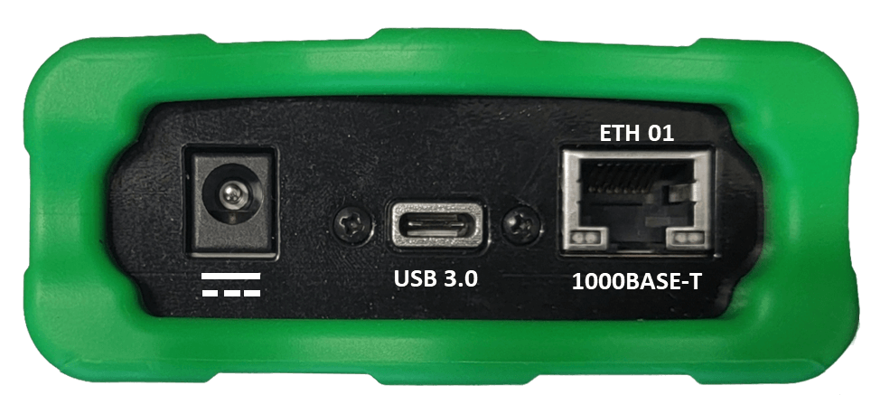
Barrel Jack (Left):
The device can be powered using a DC supply between 5.5-40V volts with a minimum power of 10 Watts. Using a power supply that does not meet these requirements may cause the device to malfunction or be permanently damaged.
USB Type C (Center):
This serves as a connection to a host computer for configuration, firmware updates, and PHY register access.
Note
RAD-Comet3 cannot be powered by the USB connection.
ETH 01 (Right)
The industry standard RJ-45 Ethernet jack is a 10/100/1000BASE-T port that can be used to connect to a host computer or be used as a network port for sending and receiving Ethernet traffic.
Link LED (Green): Indicates that a valid link has been established between your device and another 10/100/1000 Ethernet device.
Activity LED (Orange): Flashes when traffic passes in either direction over the attached Ethernet cable.
In normal operation you should see the Link LED always on, and the Activity LED flashing at a variable rate, with faster flashing meaning that more data is being transferred.
3.3.2. Ethernet Interfaces
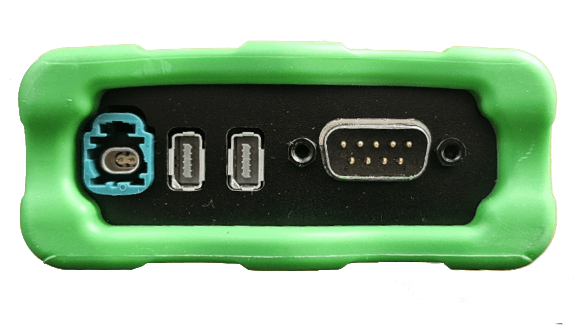
AE01
The H-MTD connector on the left is a 100/1000BASE-T1 port with the following following pin assignments.
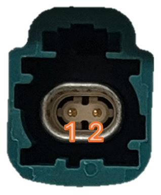
H-MTD Connector Pinout |
||
Pin # |
Label |
Description |
1 |
TRD+ |
Data transmit and receive, positive |
2 |
TRD- |
Data transmit and receive, negative |
AE02 - AE05
The left IX connector contains 4x 10BASE=T1S ports. Unlike the daisy-chain (in/out) configuration on the RAD-Comet2, each port is connected to only 2 pins.
PIN |
FUNCTION |
Cable Color |
1 |
AE_02_P |
white/orange |
2 |
AE_02_N |
orange |
3 |
GND |
– |
4 |
AE_04_P |
blue |
5 |
AE_04_N |
white/blue |
6 |
AE_03_P |
white/green |
7 |
AE_03_N |
green |
8 |
GND |
– |
9 |
AE_05_P |
white/brown |
10 |
AE_05_N |
brown |
AE06-AE07
The right IX connector contains 2x 10BASE=T1S ports. Unlike the daisy-chain (in/out) configuration on the RAD-Comet2, each port is connected to only 2 pins.
PIN |
FUNCTION |
Cable Color |
1 |
AE_06_P |
white/orange |
2 |
AE_06_N |
orange |
3 |
GND |
– |
4 |
NC |
blue |
5 |
NC |
white/blue |
6 |
AE_07_P |
white/green |
7 |
AE_07_N |
green |
8 |
GND |
– |
9 |
NC |
white/brown |
10 |
NC |
brown |
3.3.3. DB-9 Connector
The DB-9 connector on the right holds two CAN FD channels, 1 LIN Channel, and can also be used to power the RAD-Comet2. Pin assignments are listed in the table below. See this section for detail on power supply requirements.
Pin |
Signal |
|---|---|
1 |
LIN (Must use isolated GND) |
2 |
CAN 1 L |
3 |
Isolated GND |
4 |
CAN 2 L |
5 |
GND |
6 |
Isolated GND |
7 |
CAN 1 H |
8 |
CAN 2 H |
9 |
VBATT |