4. Hardware Setup
4.1. Connection Diagrams
Hookup diagrams show at a glance on how to physically connect your ValueCAN 4-1 to vehicle networks and your PC.
4.1.1. Deutsch 9-Pin Hardware Connection Diagram

Figure 7: Connector Diagram with ValueCAN Deutsch 9-Pin (J1939-RP1210) Cable (DB-9F to Deutsch 9-Pin) Part # J1939-CABLE
4.1.2. OBD II Hardware Connection Diagram
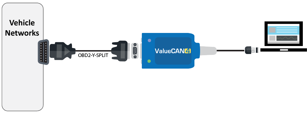
Figure 8: Connector Diagram with ValueCAN OBD-II Cable (DB-9F to OBD-11) Part # OBD2-Y-SPLIT
4.1.3. DB9 Y - Splitter Cable Hardware Hookup Diagram
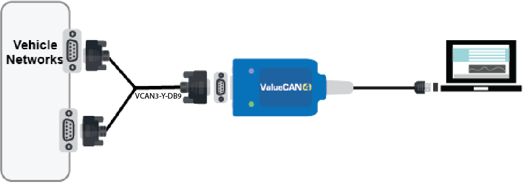
Figure 9: Connector Diagram with ValueCAN DB9 2x Y-Splitter Cable Part # VCAN3-Y-DB9
4.2. Vehicle Network and Power Connections
The integrated DB9 connector is used to connect to the vehicle/bench CAN network.
Caution
Caution: The ValueCAN 4-1 can only be powered via the USB cable.
Caution
Caution: CoreMini scripts run when the device is powered and not connected to a PC’s USB port (that is, enumerated). Therefore to run a script stand alone, it is recommended to use a power-only USB cable to prevent enumeration. Using a charger or power pack to power the ValueCAN 4-1 will also work
4.3. PC Connection
Connect the USB Type A/Type C to USB port on the PC. It is possible to use a powered USB hub to connect the ValueCAN 4-1, but performance varies due to the quality of the hub and its ability to provide power. Make sure to use a high-power USB hub and test the hub with the ValueCAN 4-1 before use.