3. A Tour of neoVI FIRE2 Hardware
Let’s now take a short tour of the neoVI FIRE 2’s hardware. We’ll examine the device from all sides, showing its external components and explaining what each does. This will help you become more familiar with the unit so you can more easily set up, configure and use it.
Like many Intrepid products, the neoVI FIRE 2 is designed so that all of its connectors are located on its sides, making the device easier to use in cramped quarters. We’ll refer to these as the left side and right side of the unit, as oriented when facing the device with its top label text readable.
Warning
The neoVI FIRE 2 is a complex device that does not contain any user-serviceable parts. Do not attempt to open the case of the neoVI FIRE 2 unless specifically instructed to do so by an Intrepid Control Systems technician, or you risk possible injury or damage to the unit.
3.1. Case and Overall Design
The neoVI FIRE 2 is enclosed in a sturdy black-anodized metal case. The device has been designed and tested for in-vehicle use, and is operational in a temperature range from -40°C to +85°C. An overall view of the neoVI FIRE 2 can be seen in Figure 3.
Connectors and ports are often a point of failure with hardware devices. To ensure that the neoVI FIRE 2 provides you with years of reliable service, Intrepid has ruggedized the physical interfaces on the device by using reinforced metal connectors.
To further protect the device against bumps and drops, it has cyan-colored rubber bumpers on both ends. These bumpers are removable, but there is no need to do this under normal circumstances, and we recommend that you leave them in place.
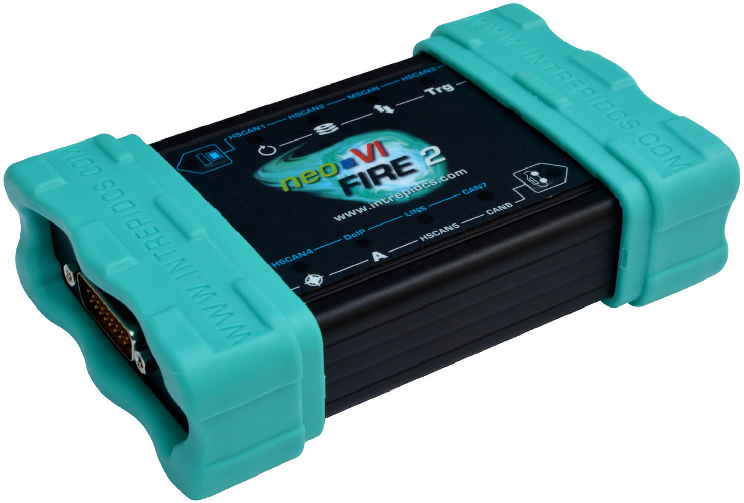
Figure 3: Overview of the neoVI FIRE 2.
The bottom of the neoVI FIRE 2 contains useful reference information, including the device serial number, pinouts of its HD-26 and µDB-9 connectors, and Intrepid’s contact information (Figure 4). Pinouts for all FIRE 2 connectors and cables can be found in Chapter 8.
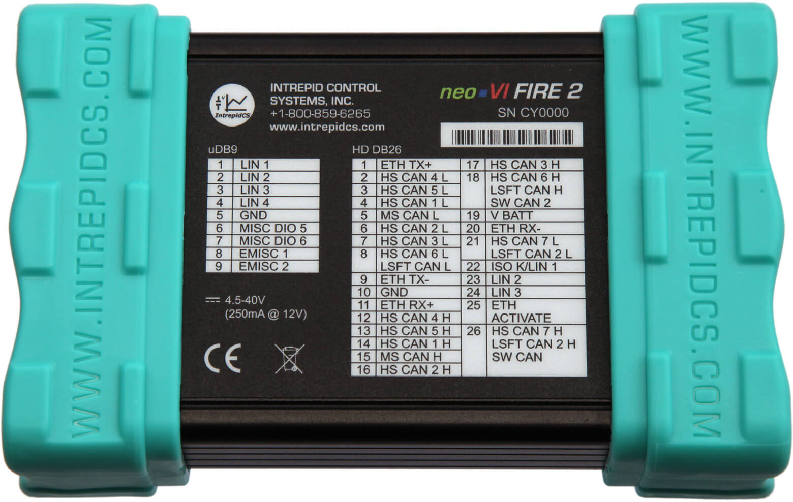
Figure 4: neoVI FIRE 2 Bottom View. Note that the FIRE 2’s miscellaneous I/O channels are “EMISC 1” and “EMISC 2”. (The “MISC DIO 5” and “MISC DIO 6” entries will be removed in future FIRE 2 label printings.)
3.2. Left Side Interfaces and Connectors
The left side of the neoVI FIRE 2 contains two components: the HD-26 connector and a set of red and green LEDs (Figure 5).
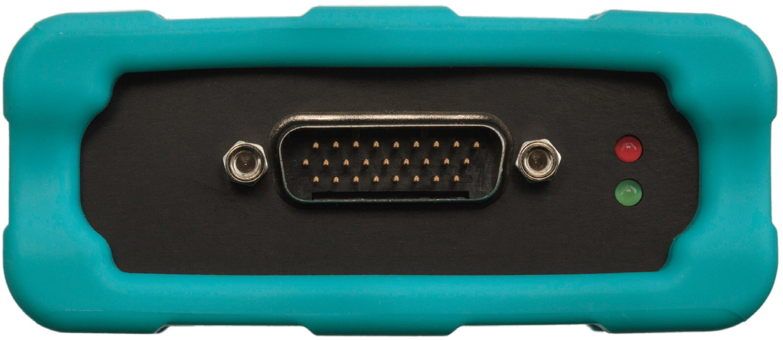
Figure 5: neoVI FIRE 2 Left Side View.
HD-26 Network Interface Connector
This male, high-density, 26-pin D-subminiature connector is the primary means by which the neoVI FIRE 2 interfaces with vehicle networks. One of two network interface cables is connected to this port, enabling CAN, LIN and Ethernet messages to be passed between the network and the FIRE 2. This connector also provides primary power to the device.
Green and Red Status LEDs
You can determine the status of the neoVI FIRE 2 by observing the blink pattern of these two LEDs. The patterns here will be identical to those seen in the keypad button LEDs on the top membrane panel (explained in Section 3.4). The membrane LEDs will usually be more convenient to use, but the traditional side panel LEDs have been preserved for those who are accustomed to them from working with the original neoVI FIRE.
3.3. Right Side Interfaces and Connectors
This side of the neoVI FIRE 2 contains most of its connectors, ports and slots (Figure 6).
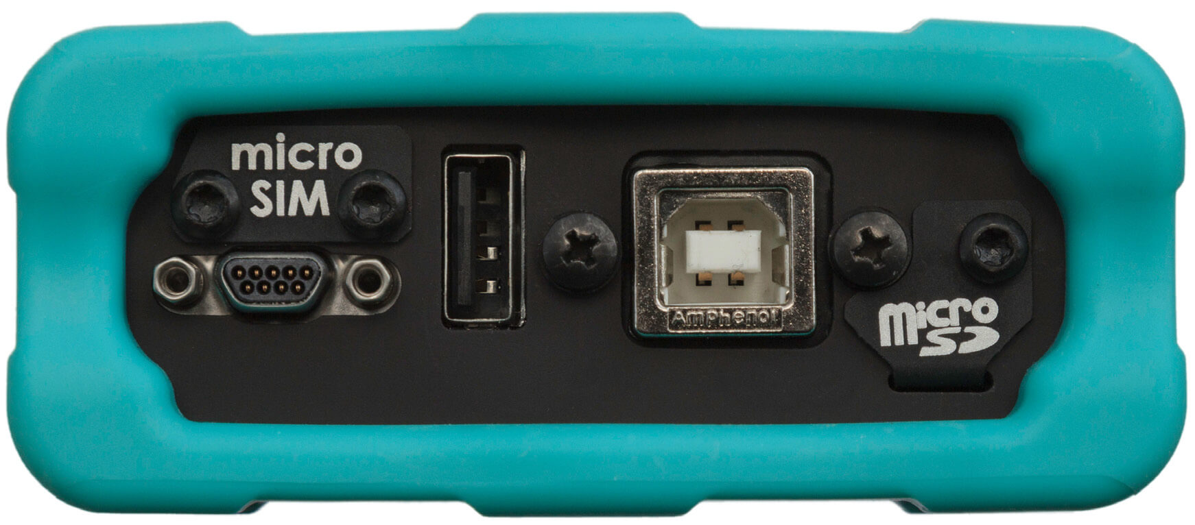
Figure 6: neoVI FIRE 2 Right Side View.
USB “B” Connector
This is the “square” connector for USB devices that use detachable cables. (The standard “rectangular” connectors found on PCs are “A” connectors, which is why the cable supplied with the neoVI FIRE 2 is often called a “USB A/B cable”.)
µDB-9 (Micro DB-9) Connector
This connector carries LIN and miscellaneous I/O signals to and from the FIRE 2. A micro DB-9 was used to allow the device to be made more compact; a provided cable converts from this smaller connector to the standard DB-9 commonly used in the automotive industry.
USB Host Port
The USB “A” connector allows the FIRE 2 to act as a USB host, so other devices can plug into it. Please see Section 7.2 for more details.
microSD Slot and Cover
This slot holds the microSD card that stores data logged or captured by the neoVI FIRE 2. It is protected by a metal cover that prevents accidental ejection of the card and protects the slot from dirt and debris.
You can download the contents of the installed microSD card over USB, or for larger data sets, remove the card and use the provided external card reader.
Micro-SIM Slot and Cover
This slot can be used to hold a Micro-SIM card. Like the microSD card slot, it is covered with a metal plate to protect it and the device.
3.4. Membrane LED Display and Keypad
One of the neoVI FIRE 2’s many improvements over the original neoVI FIRE is the addition of a membrane LED display and keypad on top of the unit (Figure 7). The membrane contains 10 LEDs that provide immediate visual feedback about the status of the device, and two keypad buttons that can be used to toggle the indicator mode and for other functions.
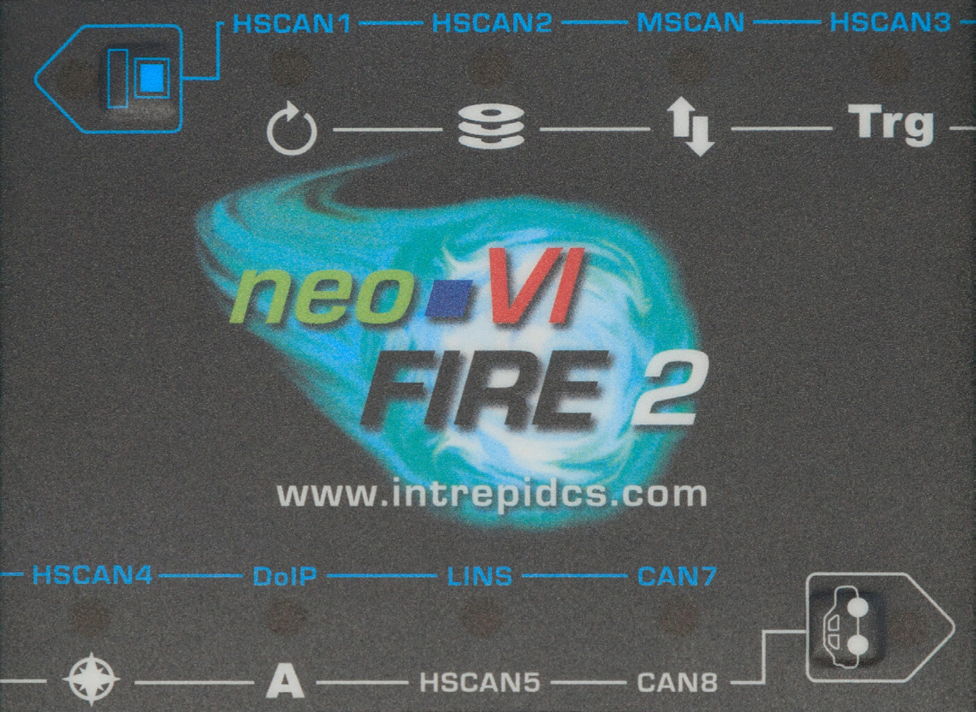
Figure 7: neoVI FIRE 2 Membrane LED Display and Keypad.
All of the LEDs and buttons are also scriptable: the buttons can be used for user input, and the LEDs can be set to provide information from a CoreMini program running in the FIRE 2.
Keypad Buttons and LEDs
There are two keypad buttons on the neoVI FIRE 2’s top membrane: one with a blue computer icon located near the top left, and one with a white car icon located near the bottom right. Pressing either button toggles the meaning of the 8 RGB LEDs on the membrane as follows:
Blue Button (Top Left): When pressed, activates the “blue set” of LED meanings: each RGB LED shows the status of the network whose name appears in a blue label above it. This set is active in the image in Figure 8.
White Button (Bottom Right): When pressed, activates the “white set” of LED meanings: each RGB LED shows information about a network or FIRE 2 function based on the white icon or label below it
The buttons themselves also contain red and green LEDs, which flash in the same pattern as the red and green LEDs on the left side of the device (see Section 3.2). The illuminated LEDs show which set of indicator meanings is active, and may also be more convenient for monitoring general device status than the left-side LEDs.
The green and red status LEDs here, and on the side of the neoVI FIRE 2, show information about it through a number of flash patterns, which are described in Table 1 .
Flash Pattern |
Description |
|---|---|
Green LED flashing rapidly; red LED off |
FIRE 2 is powered on but offline. |
Green and red LEDs flashing rapidly in alternating sequence |
Device is powered and online with a PC running Vehicle Spy or other software. |
Red LED flashing rapidly; green LED off |
FIRE 2 is running a CoreMini script. |
Red LED flashing at constant rate; green LED flashing intermittently |
VehicleScape Standalone Logging is active; the flash rate of the green LED reflects the rate at which data is being logged. |
Green LED flashes three times slowly, red LED flashes once, then cycle repeats |
FIRE 2 is in bootloader mode. This normally occurs when new firmware is being flashed to the device. See Section 5.2 for more details. |
Network/Logger Status RGB LEDs
The membrane contains 8 RGB (full color) LEDs in two rows of four. The meaning of each LED changes depending on whether the upper left blue button has been pressed or the lower right white button, so the 8 LEDs actually indicate a total of 16 separate status conditions. To fid the current meaning of each LED, check whether the white button or blue button has its LEDs flashing, and then refer to the label of the corresponding color (described below).
Interpretation of RGB LED Colors
These are “RGB” LEDs because they contain separate red, green and blue elements. For networks, each indicates a different aspect of the device’s overall status:
Green: Device is transmitting messages on this channel.
Blue: Device is receiving messages on this channel.
Red: Device is detecting errors on this channel.
It is possible for more than one LED component to be lit, producing the following results:
Green+Blue (Cyan): Device is transmitting and receiving on this channel.
Green+Red (Yellow): Device is transmitting and detecting errors on this channel.
Blue+Red (Magenta): Device is receiving and detecting errors on this channel.
Green+Blue+Red (White): Device is transmitting, receiving and detecting errors on this channel.
Figure 8 shows a photograph of the top membrane of a FIRE2 in active use, with the blue set of status indicators active, meaning that transmissions are occurring on fie channels and errors on one.
As a further cue to network activity, the intensity of these LEDs is proportional to the amount of traffic on the corresponding network. Slower traffic on a network will cause the network’s LED to flash more dimly, while heavy traffic will cause the LED to be brighter. Note that the blink rate remains the same regardless of traffic level.
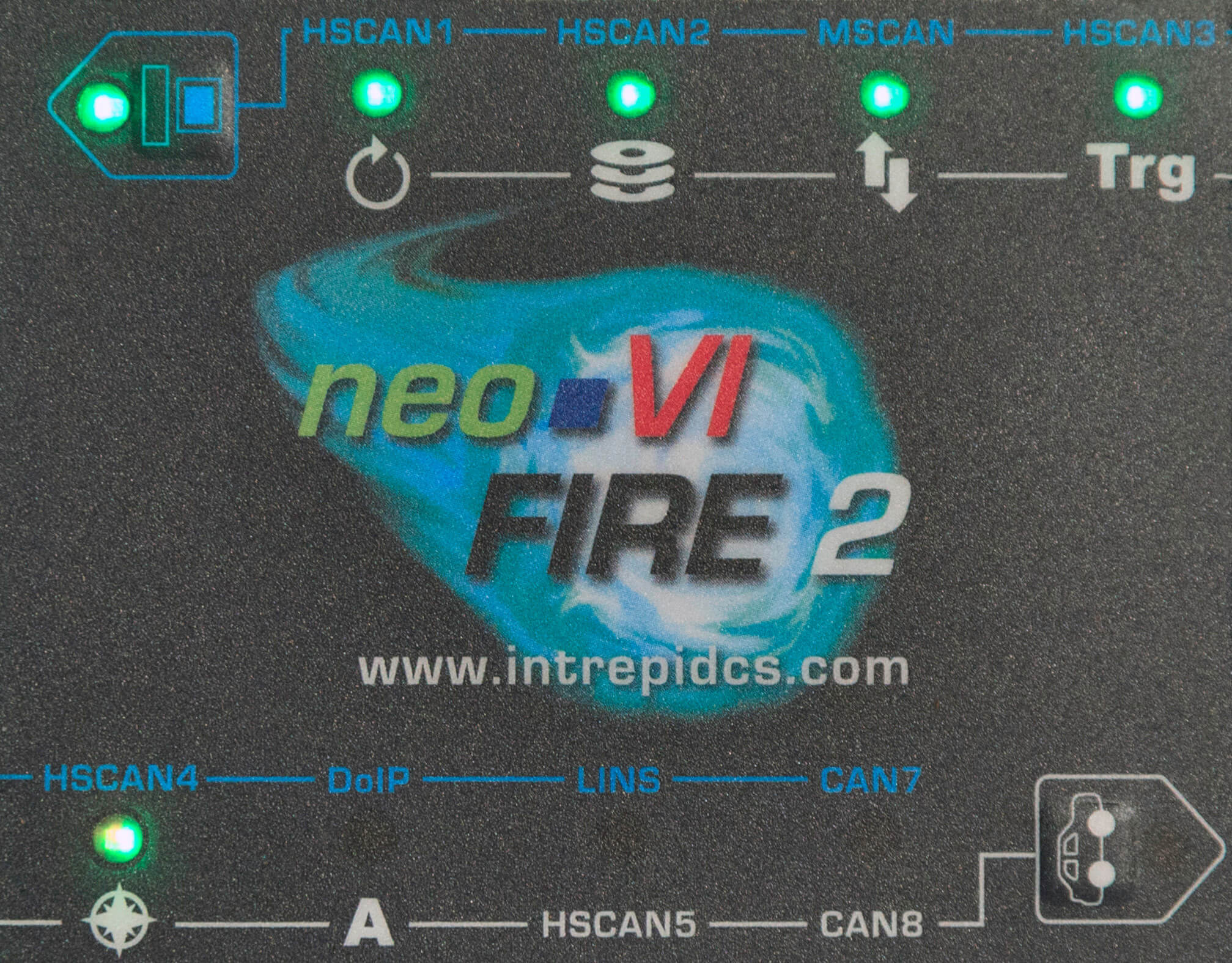
Figure 8: neoVI FIRE 2 Membrane LED Display and Keypad Showing Active LEDs.** In this image, the blue set of LED meanings is active, as indicated by the green LED being lit within the blue computer icon in the top left corner (this LED alternates between green and red when the device is online). The other LEDs thus mean that the neoVI FIRE 2 is active and transmitting on the HSCAN1, HSCAN2, MSCAN, HSCAN3 and HSCAN4 channels (in use these all flash a few times per second.) Note that the LED for HSCAN4 is actually yellowish; it is flashing both a bright green and a dim red to indicate errors while transmitting on the HSCAN4 channel.
“Blue Set” LED Status Indicators
Table 2 lists the blue labels on the FIRE 2 membrane interface, and describes the meaning of the LED associated with each when the blue set is selected (top left keypad button flashing). The LEDs are listed from top to bottom, left to right, as seen looking at the membrane in its usual orientation.
Label |
Description |
|---|---|
HSCAN1 |
Transmit / receive / error status of HS CAN channel 1 |
HSCAN2 |
Transmit / receive / error status of HS CAN channel 2 |
MSCAN |
Transmit / receive / error status of MS CAN channel |
HSCAN3 |
Transmit / receive / error status of HS CAN channel 3 |
HSCAN4 |
Transmit / receive / error status of HS CAN channel 4 |
DoIP |
Transmit / receive / error status of Ethernet channel |
LINS |
Status of all LIN channels |
CAN7 |
Transmit / receive / error status of HS CAN channel 6, SW CAN channel 2, or LSFT CAN channel 1, depending on CAN mode selected (see Section 5.5) |
“White Set” LED Status Indicators
Table 3 lists the white labels/icons on the FIRE 2 membrane interface, and describes the meaning of the LEDs for each when the white set is selected (bottom right keypad button flashing). Again the LEDs are listed from top to bottom, left to right
Label/Icon |
Description |
|---|---|
|
CoreMini script active |
|
Disk (solid state drive) activity |
|
Data being uploaded |
|
Logging a triggered collection after the trigger condition has activated |
|
GPS lock (using neoVI MIC2, available later in 2016) |
|
General purpose, user-programmable |
HSCAN5 |
Transmit / receive / error status of HS CAN channel 5 |
CAN8 |
Transmit / receive / error status of HS CAN channel 7, SW CAN channel 1, or LSFT CAN channel 2, depending on CAN mode selected (see Section 5.5) |


3.5. Standard Cables and Cable Options
As mentioned in Section 2.2, the FIRE 2 ships with several standard cables, as well as one of fie optional OBD cables that was selected when the device was ordered. We’ll now illustrate these cables and describe each one’s use. Connector pinouts and cable signal tables for this hardware can be found in Chapter 8 (except for the USB cable, which is industry standard).
USB “A/B” Cable
This is a standard cable is used to connect PCs or other hosts to USB devices that do not have integrated cables (Figure 9). The detachable cable makes the FIRE 2 easier to transport than would be the case if it were built in, and also allows the cable to be easily replaced if it is ever damaged.
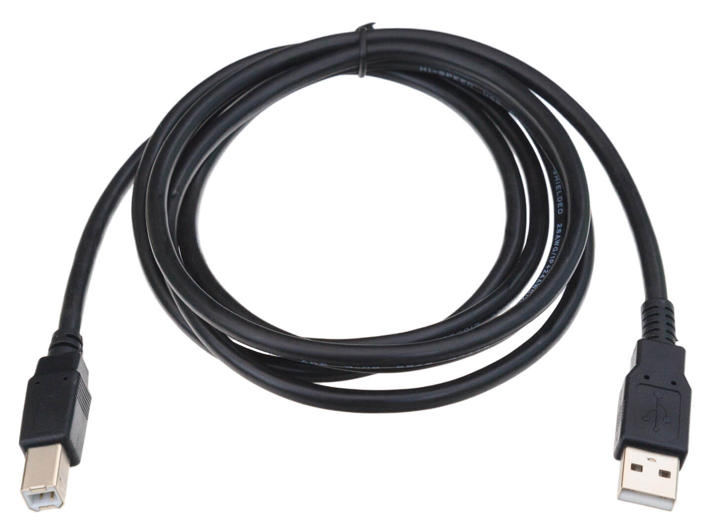
Figure 9: USB “A/B” Cable.
µDB-9 (Micro DB-9) to DB-9 Cable
As mentioned in Section 3.3, a µDB-9 connector was used on the FIRE 2 to allow it to be made smaller. This is a “straight-through” cable that adapts the smaller connector to the regular DB-9 used in automotive applications. The cable can be seen in Figure 10, while a close-up of the special µDB-9 connector is in Figure 11 .
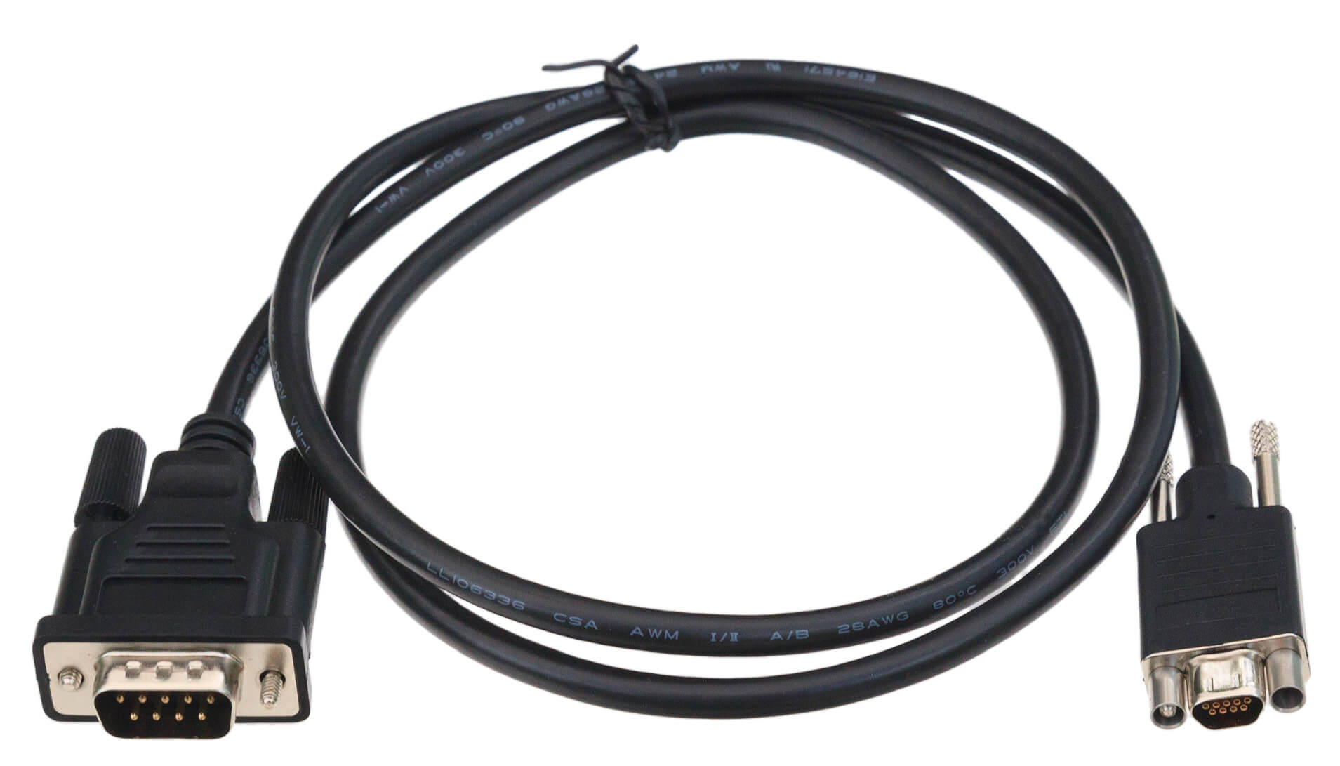
Figure 10: µDB-9 (Micro DB-9) to DB-9 Cable
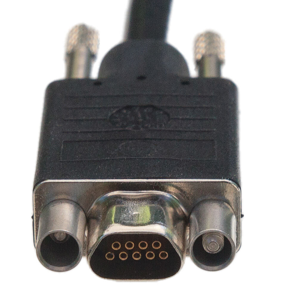
Figure 11: Close-up of µDB-9 Connector. This connector attaches to the mating connector on the neoVI FIRE 2, adapting it into an industry-standard DB-9 connector.
FIRE 2 Ethernet Cable Adapter
This special cable “breaks out” the HD-26 connector on the left side of the neoVI FIRE 2 to three connectors that are used to communicate with vehicle networks. The cable is illustrated in Figure 12, while the network interface connectors are described further below.
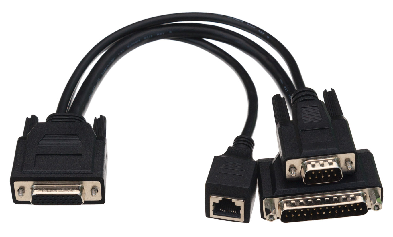
Figure 12: FIRE 2 Ethernet Cable Adapter. This cable allows the FIRE 2 to connect to vehicle networks and receive its primary power input.
DB-25 Connector
This is the main vehicle network interface connector, carrying CAN, LIN and Ethernet messages, as well as providing power to the FIRE 2 from the network (Figure 13). As we’ll see later in the manual, it is also used to connect an additional cable for OBD applications.
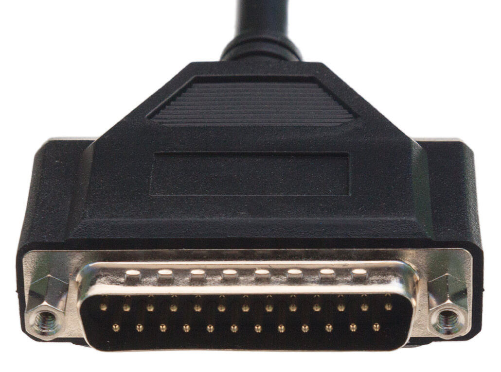
Figure 13: DB-25 Connector. This connector carries main network traffic and primary DC power to the FIRE 2.
DB-9 Connector
This connector carries 4 LIN channels for LIN applications (Figure 14).
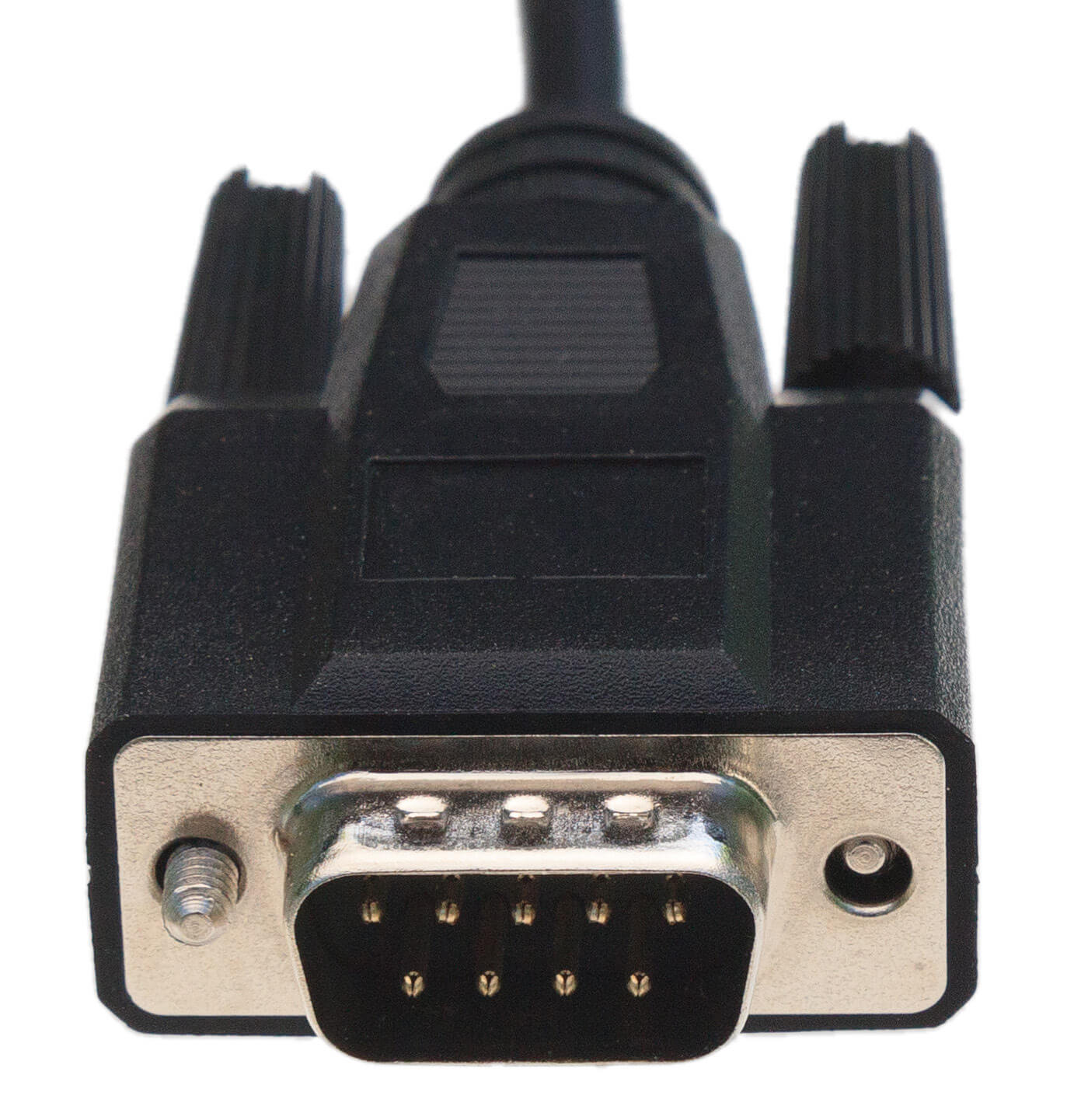
Figure 14: DB-9 Connector. This industry-standard connector carries LIN traffic
RJ-45 Connector
This female RJ-45 socket is used to attach a standard Ethernet cable for Automotive Ethernet and DoIP applications (Figure 15).
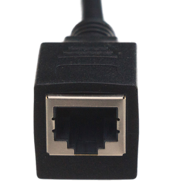
Figure 15: RJ-45 Socket.
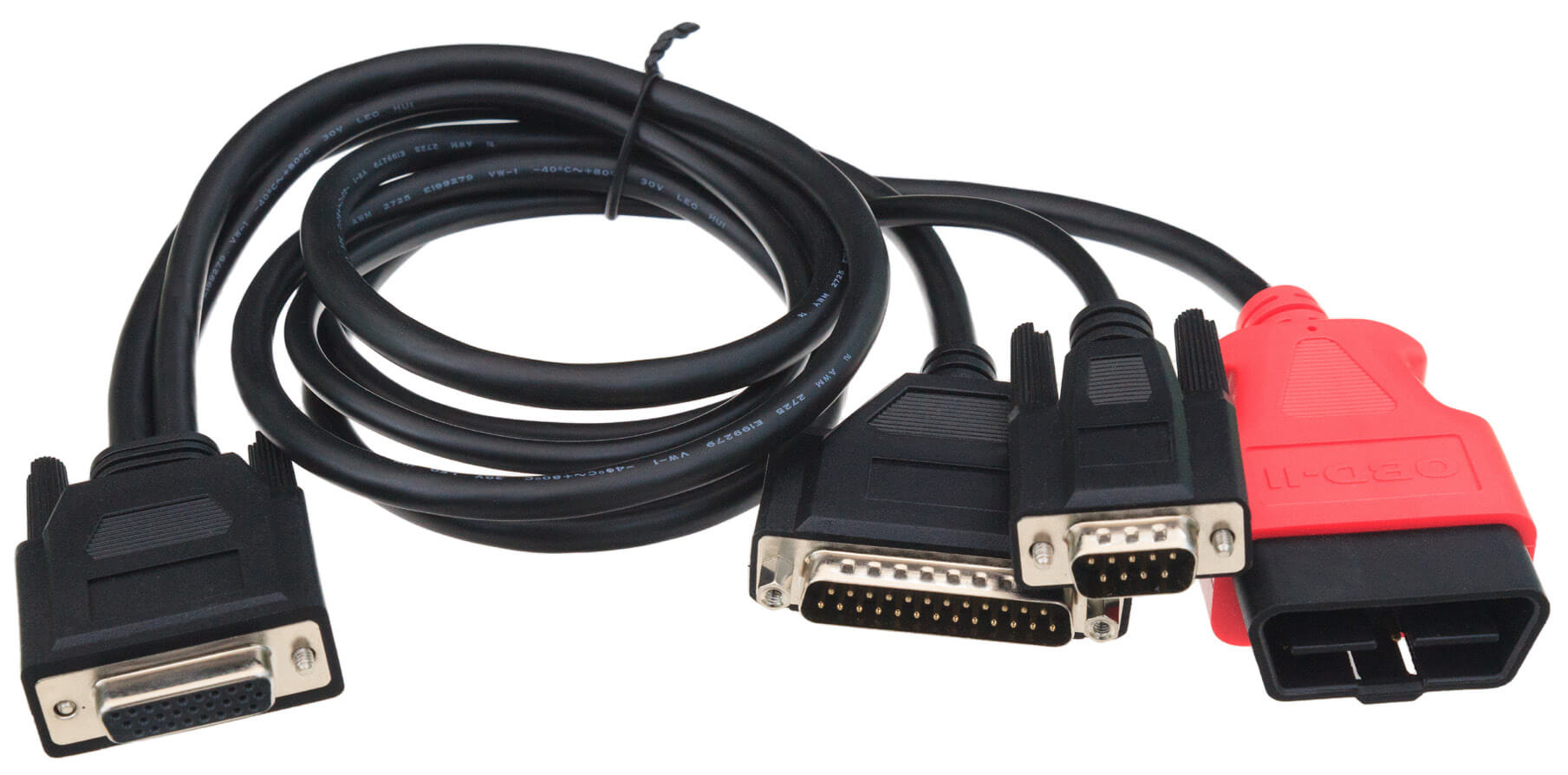
OBD Cables
The FIRE 2 comes with your choice of one of fie OBD cables, which are used to interface the device to a vehicle or bench OBD port. Four of these cables attach to the DB-25 connector on the FIRE 2 Ethernet Cable Adapter (Figure 13), while the fifth actually takes the place of that cable, connecting directly to the FIRE 2.
See Section 4.3 for hookup diagrams that show how to connect all of these cables to the FIRE 2 and your network or bench.
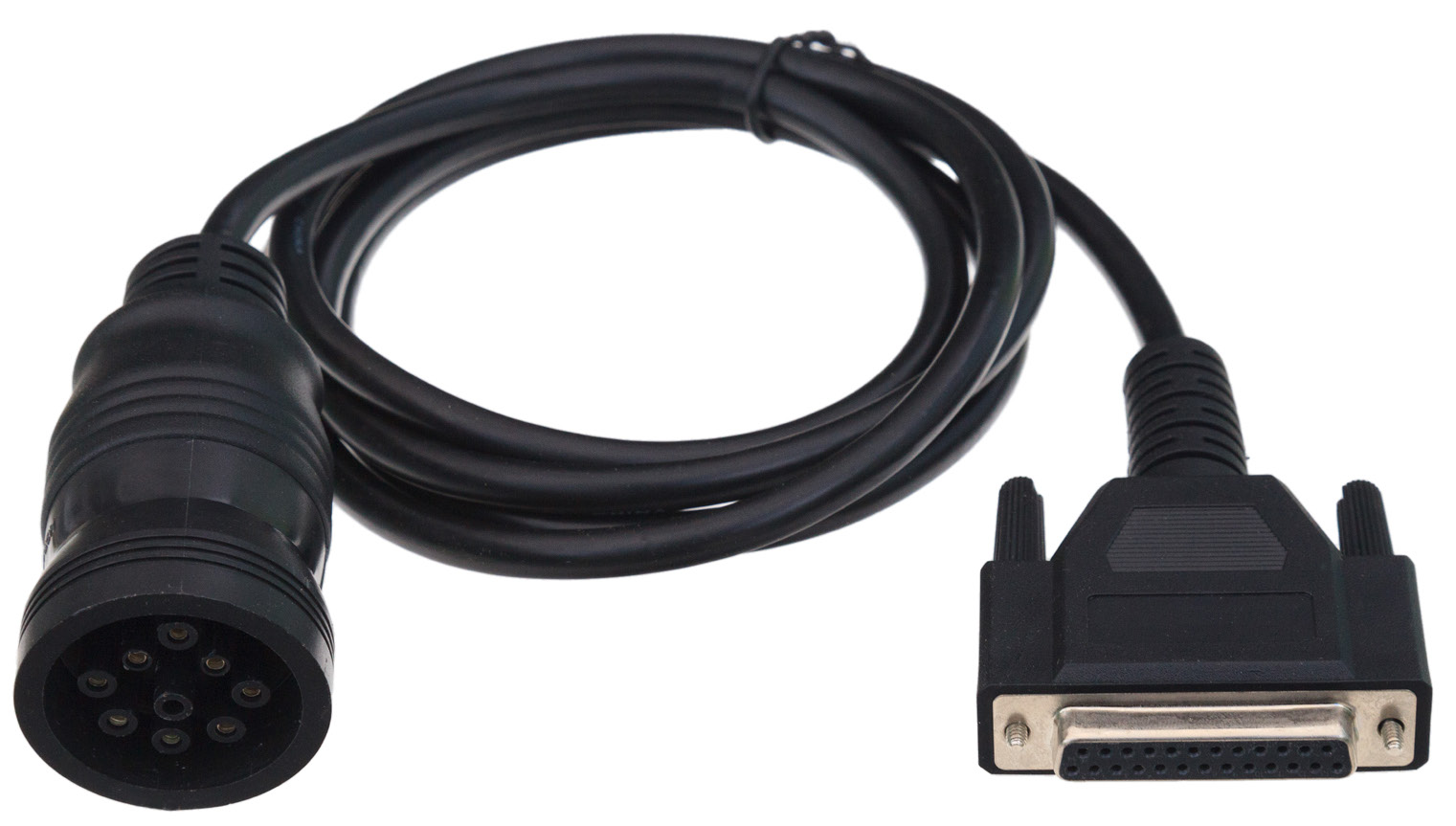
neoVI-OBD-1 Cable
This cable, which has a red OBD-II connector, is used primarily for General Motors vehicles. It can be seen in Figure 16.
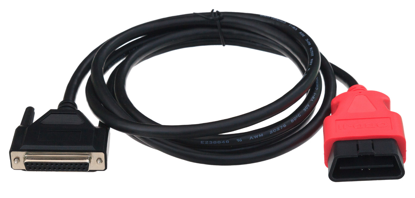
Figure 16: neoVI-OBD-1 Cable.
neoVI-OBD-MULTI Cable
This cable has a standard black OBD-II connector and is suitable for use with the vehicles of most OEMs. It is pictured in Figure 17.
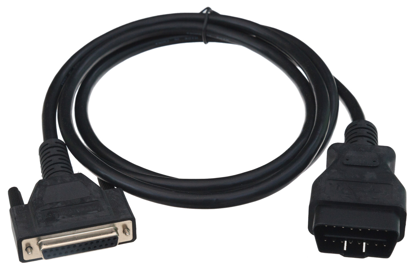
Figure 17: neoVI-OBD-MULTI Cable.
neoVI-OBD-MULTI Right Angle Cable
This is the same as the neoVI-OBD-MULTI cable but terminates with a right-angled OBD II connector for vehicles where this is required. A picture of the cable is shown in Figure 18.
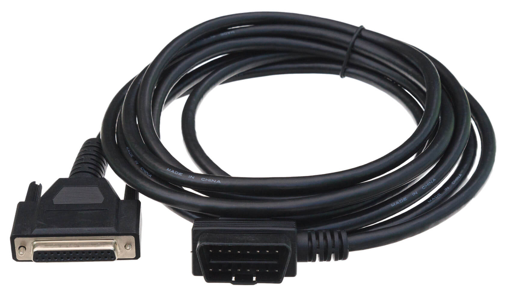
Figure 18: neoVI-OBD-MULTI Right Angle Cable.