8. Reference: Connector Pinouts and Cable Signal Mappings
This section contains complete pinouts for the connectors on the neoVI FIRE 2, as well as those on the network interface cables used to attach to it. For your convenience, tables are also provided that show the mappings of signals between pin numbers on the connectors of each network cable.
Note that the USB cable is industry standard and not covered here.
8.1. neoVI FIRE 2 Connector Pinouts
We’ll start with the pinouts for the connectors on the neoVI FIRE 2 itself.
HD-26 Connector Pinout
A list of pin assignments for the HD-26 connector can be found in Table 4, with pin numbering for the connector illustrated in Figure 86.
Pin # |
Name |
Description |
|---|---|---|
1 |
ETH TX + |
Ethernet transmit channel, positive |
2 |
HS CAN 4 L |
High Speed CAN channel 4, low |
3 |
HS CAN 5 L |
High Speed CAN channel 5, low |
4 |
HS CAN 1 L |
High Speed CAN channel 1, low |
5 |
MS CAN L |
Medium Speed CAN channel, low |
6 |
HS CAN 2 L |
High Speed CAN channel 2, low |
7 |
HS CAN 3 L |
High Speed CAN channel 3, low |
8 |
HS CAN 6 L / LSFT CAN L |
High Speed CAN channel 6, low / Low Speed Fault Tolerant CAN channel 1, low |
9 |
ETH TX- |
Ethernet transmit channel, negative |
10 |
GND |
Ground |
11 |
ETH RX+ |
Ethernet receive channel, positive |
12 |
HS CAN 4 H |
High Speed CAN channel 4, high |
13 |
HS CAN 5 H |
High Speed CAN channel 5, high |
14 |
HS CAN 1 H |
High Speed CAN channel 1, high |
15 |
MS CAN H |
Medium Speed CAN channel, high |
16 |
HS CAN 2 H |
High Speed CAN channel 2, high |
17 |
HS CAN 3 H |
High Speed CAN channel 3, high |
18 |
HS CAN 6 H / LSFT CAN H / SW CAN 2 |
High Speed CAN channel 6, high / Low Speed Fault Tolerant CAN channel 1, high / Single Wire CAN channel 2 |
19 |
V BATT |
DC Input Power |
20 |
ETH RX- |
Ethernet receive channel, negative |
21 |
HS CAN 7 L / LSFT CAN 2 L |
High Speed CAN channel 7, low / Low Speed Fault Tolerant CAN channel 2, low |
22 |
ISO K/LIN 1 |
LIN channel 1 |
23 |
LIN 2 |
LIN channel 2 |
24 |
LIN 3 |
LIN channel 3 |
25 |
ETH ACTIVATE |
Ethernet activation line |
26 |
HS CAN 7 H / LSFT CAN 2 H / SW CAN |
High Speed CAN channel 7, high / Low Speed Fault Tolerant CAN channel 2, high / Single Wire CAN channel 1 |
Table 4: neoVI FIRE 2 HD-26 Connector Pinout.
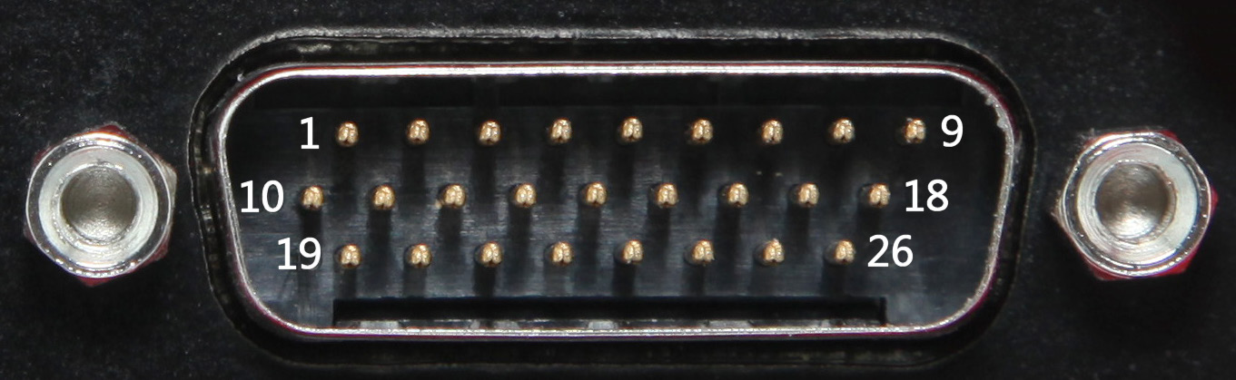
Figure 86: neoVI FIRE 2 HD-26 Connector Pin Numbering.
µDB-9 Connector Pinout
The pinout for the µDB-9 connector on the FIRE 2 can be seen in Figure 87 and Table 5. Note that the I/O channel numbering (which skips 3 and 4) is designed to ensure backward compatibility with the original neoVI FIRE.
Pin # |
Name |
Description |
|---|---|---|
1 |
LIN 1 |
LIN channel 1 |
2 |
LIN 2 |
LIN channel 2 |
3 |
LIN 3 |
LIN channel 3 |
4 |
LIN 4 |
LIN channel 3 |
5 |
GND |
LIN channel 3 |
6 |
N/C |
LIN channel 3 |
7 |
N/C |
LIN channel 3 |
8 |
EMISC 1 |
Enhanced miscellaneous I/O channel 1 (analog or digital with PWM and 0-40V support) |
8 |
EMISC 2 |
Enhanced miscellaneous I/O channel 2 (analog or digital with PWM and 0-40V support) |
Table 5: neoVI FIRE 2 µDB-9 Connector Pinout.
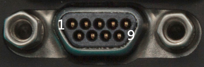
Figure 87: neoVI FIRE 2 µDB-9 Connector Pin Numbering.
8.2. FIRE 2 Ethernet Cable Adapter Connector Pinouts and Signal Mapping
The primary cable for connecting the FIRE 2 to vehicle networks has four connectors: HD- 26, DB-25, DB-9 and RJ-45. The HD-26 connector mates to the HD-26 on the FIRE 2 and uses the same pinout shown in Table 4; the others are described below, followed by a signal mapping table.
DB-25 Connector Pinout
Table 6 lists the pins of the DB-25 connector on the FIRE 2 Ethernet Cable Adapter.
Pin # |
Name |
Description |
|---|---|---|
1 |
HS CAN 7 H / LSFT CAN 2 H / SW CAN |
High Speed CAN channel 7, high / Low Speed Fault Tolerant CAN channel 2, high / Single Wire CAN channel 1 |
2 |
N/C |
No connection |
3 |
HS CAN 6 H / LSFT CAN H / SW CAN 2 |
High Speed CAN channel 6, high / Low Speed Fault Tolerant CAN channel 1, high / Single Wire CAN channel 2 |
4 |
HS CAN 6 L / LSFT CAN L |
High Speed CAN channel 6, low / Low Speed Fault Tolerant CAN channel 1, low |
5 |
MS CAN H |
Medium Speed CAN channel, high |
6 |
MS CAN L |
Medium Speed CAN channel, low |
7 |
HS CAN 7 L / LSFT CAN 2 L |
High Speed CAN channel 7, low / Low Speed Fault Tolerant CAN channel 2, low |
8 |
ISO K/LIN 1 |
K-Line channel 1 / LIN channel 1 |
9 |
N/C |
No connection |
10 |
N/C |
No connection |
11 |
N/C |
No connection |
12 |
N/C |
No connection |
13 |
GND |
Ground |
14 |
HS CAN 1 H |
High Speed CAN channel 1, high |
15 |
HS CAN 1 L |
High Speed CAN channel 1, low |
16 |
HS CAN 2 H |
High Speed CAN channel 2, high |
17 |
HS CAN 2 L |
High Speed CAN channel 2, low |
18 |
HS CAN 4 H |
High Speed CAN channel 4, high |
19 |
HS CAN 3 H |
High Speed CAN channel 3, high |
20 |
HS CAN 3 L |
High Speed CAN channel 3, low |
21 |
HS CAN 5 H |
High Speed CAN channel 5, high |
22 |
HS CAN 5 L |
High Speed CAN channel 5, low |
23 |
HS CAN 4 L |
High Speed CAN channel 4, low |
24 |
N/C |
No connection |
25 |
V BATT |
DC Input Power |
Table 6: FIRE 2 Ethernet Cable Adapter DB-25 Connector Pinout.
DB-9 Connector Pinout
Table 7 contains the pinout for the DB-9 connector on this cable.
Pin # |
Name |
Description |
|---|---|---|
1 |
LIN 1 |
LIN channel 1 |
2 |
LIN 2 |
LIN channel 2 |
3 |
LIN 3 |
LIN channel 3 |
4 |
ETH ACTIVATE |
Ethernet activation line |
5 |
GND |
Ground |
6 |
N/C |
No connection |
7 |
N/C |
No connection |
8 |
N/C |
No connection |
9 |
N/C |
No connection |
Table 7: FIRE 2 Ethernet Cable Adapter DB-9 Connector Pinout.
RJ-45 Connector Pinout
The pinout for the RJ-45 (Ethernet) connector on this cable can be found in Table 8.
Pin # |
Name |
Description |
|---|---|---|
1 |
ETH TX+ |
Ethernet transmit channel, positive |
2 |
ETH TX- |
Ethernet transmit channel, negative |
3 |
ETH RX+ |
Ethernet receive channel, positive |
4 |
N/C |
No connection |
5 |
N/C |
No connection |
6 |
ETH RX- |
Ethernet receive channel, negative |
7 |
N/C |
No connection |
8 |
N/C |
No connection |
Table 8: FIRE 2 Ethernet Cable Adapter RJ-45 Connector Pinout.
Cable Signal Mapping
For easy reference, Table 9 shows the mapping of signals for the FIRE 2 Ethernet Cable Adapter, by pin order on the HD-26 that connects to the FIRE 2.
Signal Name |
Signal Description |
HD-26 Pin # |
DB-25 Pin # |
DB-9 Pin # |
RJ-45 Pin # |
|---|---|---|---|---|---|
ETH TX+ |
Ethernet transmit channel, positive |
1 |
1 |
||
HS CAN 4 L |
High Speed CAN channel 4, low |
2 |
23 |
||
HS CAN 5 L |
High Speed CAN channel 5, low |
3 |
22 |
||
HS CAN 1 L |
High Speed CAN channel 1, low |
4 |
15 |
||
MS CAN L |
Medium Speed CAN channel, low |
5 |
6 |
||
HS CAN 2 L |
High Speed CAN channel 2, low |
6 |
17 |
||
HS CAN 3 L |
High Speed CAN channel 3, low |
7 |
20 |
||
HS CAN 6 L / LSFT CAN L |
High Speed CAN channel 6, low / Low Speed Fault Tolerant CAN channel 1, low |
8 |
4 |
||
ETH TX- |
Ethernet transmit channel, negative |
9 |
2 |
||
GND |
Ground |
10 |
13 |
5 |
|
ETH RX+ |
Ethernet receive channel, positive |
11 |
3 |
||
HS CAN 4 H |
High Speed CAN channel 4, high |
12 |
18 |
||
HS CAN 5 H |
High Speed CAN channel 5, high |
13 |
21 |
||
HS CAN 1 H |
High Speed CAN channel 1, high |
14 |
14 |
||
MS CAN H |
Medium Speed CAN channel, high |
15 |
5 |
||
HS CAN 2 H |
High Speed CAN channel 2, high |
16 |
16 |
||
HS CAN 3 H |
High Speed CAN channel 3, high |
17 |
19 |
||
HS CAN 6 H / LSFT CAN H / SW CAN 2 |
High Speed CAN channel 6, high / Low Speed Fault Tolerant CAN channel 1, high / Single Wire CAN channel 2 |
18 |
3 |
||
V BATT |
DC Input Power |
19 |
25 |
||
ETH RX- |
Ethernet receive channel, negative |
20 |
6 |
||
HS CAN 7 L / LSFT CAN 2 L |
High Speed CAN channel 7, low / Low Speed Fault Tolerant CAN channel 2, low |
21 |
7 |
||
ISO K/LIN 1 |
LIN channel 1 |
22 |
1 |
||
LIN 2 |
LIN channel 2 |
23 |
2 |
||
LIN 3 |
LIN channel 3 |
24 |
3 |
||
ETH ACTIVATE |
Ethernet activation line |
25 |
4 |
||
HS CAN 7 H / LSFT CAN 2 H / SW CAN |
High Speed CAN channel 7, high / Low Speed Fault Tolerant CAN channel 2, high / Single Wire CAN channel 1 |
26 |
1 |
Table 9: FIRE 2 Ethernet Cable Adapter Signal Mapping.
8.3. neoVI-OBD-1 Cable Connector Pinouts and Signal Mapping
This OBD cable contains a DB-25 connector that mates to the DB-25 on the FIRE 2 Ethernet Cable Adapter and an OBD-II / J1962 connector for your vehicle or bench.
DB-25 Connector Pinout
Table 10 shows the pinout of the DB-25 connector on the neoVI-OBD-1.
Pin # |
Name |
Description |
|---|---|---|
1 |
SW CAN |
Single Wire CAN channel |
2 |
N/C |
No connection |
3 |
N/C |
No connection |
4 |
N/C |
No connection |
5 |
MS CAN H |
Medium Speed CAN channel, high |
6 |
MS CAN L |
Medium Speed CAN channel, low |
7 |
ISO L |
ISO 9141-2 L-Line |
8 |
ISO9141/K/LIN1 |
ISO 9141-2 K-Line / LIN channel 1 |
9 |
N/C |
No connection |
10 |
N/C |
No connection |
11 |
N/C |
No connection |
12 |
N/C |
No connection |
13 |
GND |
Ground |
14 |
HS CAN 1 H |
High Speed CAN channel 1, high |
15 |
HS CAN 1 L |
High Speed CAN channel 1, low |
16 |
HS CAN 2 H |
High Speed CAN channel 2, high |
17 |
HS CAN 2 L |
High Speed CAN channel 2, low |
18 |
N/C |
No connection |
19 |
HS CAN 3 H |
High Speed CAN channel 3, high |
20 |
HS CAN 3 L |
High Speed CAN channel 3, low |
21 |
N/C |
No connection |
22 |
N/C |
No connection |
23 |
N/C |
No connection |
24 |
N/C |
No connection |
25 |
V BATT |
DC Input Power |
Table 10: neoVI-OBD-1 Cable DB-25 Connector Pinout.
OBD-II / J1962 Connector Pinout
Table 11 contains the pinout for the OBD-II / J1962 connector on this cable.
Pin # |
Name |
Description |
|---|---|---|
1 |
Discretionary (SW CAN) |
Single Wire CAN channel |
2 |
J1850 + |
J1850 line, positive |
3 |
Discretionary (MS CAN H) |
Medium Speed CAN channel, high |
4 |
Chassis GND |
Chassis Ground |
5 |
Signal GND |
Signal Ground |
6 |
Discretionary (HS CAN H) |
High Speed CAN channel, high |
7 |
ISO9141/K/LIN1 |
ISO 9141-2 K-Line / LIN channel 1 |
8 |
Discretionary |
Discretionary |
9 |
Discretionary (ALDL) |
Assembly Line Diagnostics Link |
10 |
J1850 - |
J1850 line, negative |
11 |
Discretionary (MS CAN L) |
Medium Speed CAN channel, low |
12 |
Discretionary |
Discretionary |
13 |
Discretionary |
Discretionary |
14 |
Discretionary (HS CAN L) |
High Speed CAN channel, low |
15 |
ISO L |
ISO 9141-2 L-Line |
16 |
VBATT |
Unswitched Vehicle Battery Positive |
Table 11: neoVI-OBD-1 Cable OBD-II / J1962 Connector Pinout. The table shows standard signals for the OBD-II connector; this includes J1850, which is not supported by the NEOVI FIRE 2.
Cable Signal Mapping
Table 12 contains the mapping of signals for the neoVI-OBD-1 cable. The signal names for both connectors are shown and the table is based on the OBD-II connector’s pin order.
OBD-II Pin # |
OBD-II Signal |
DB-25 Signal |
DB-25 Pin # |
|---|---|---|---|
1 |
Discretionary (SW CAN) |
SW CAN |
1 |
2 |
J1850 + |
N/C |
2 |
3 |
Discretionary (MS CAN H) |
MS CAN H |
5 |
4 |
Chassis GND |
N/C |
N/C |
5 |
Signal GND |
GND |
13 |
6 |
Discretionary (HS CAN H) |
HS CAN 1 H |
14 |
7 |
ISO9141/K/LIN1 |
ISO9141/K/LIN1 |
8 |
8 |
Discretionary |
N/C |
N/C |
9 |
Discretionary (ALDL) |
HS CAN 3 H |
19 |
10 |
J1850 - |
HS CAN 3 L |
20 |
11 |
Discretionary (MS CAN L) |
MS CAN L |
6 |
12 |
Discretionary |
HS CAN 2 H |
16 |
13 |
Discretionary |
HS CAN 2 L |
17 |
14 |
Discretionary (HS CAN L) |
HS CAN 1 L |
15 |
15 |
ISO L |
ISO L |
7 |
16 |
VBATT |
VBATT |
25 |
Table 12: neoVI-OBD-1 Cable Signal Mapping.
8.4. neoVI-OBD-MULTI (Regular and Right Angle) Cable Connector Pinouts and Signal Mapping
These two cables have the same pinouts and signal mappings, as they differ only in the physical construction of the OBD-II connector.
DB-25 Connector Pinout
Table 13 shows the pinout of the DB-25 connector on the neoVI-OBD-1.
Pin # |
Name |
Description |
|---|---|---|
1 |
N/C |
No connection |
2 |
N/C |
No connection |
3 |
N/C |
No connection |
4 |
N/C |
No connection |
5 |
MS CAN H |
Medium Speed CAN channel, high |
6 |
MS CAN L |
Medium Speed CAN channel, low |
7 |
ISO L |
ISO 9141-2 L-Line |
8 |
ISO9141/K/LIN1 |
ISO 9141-2 K-Line / LIN channel 1 |
9 |
N/C |
No connection |
10 |
N/C |
No connection |
11 |
N/C |
No connection |
12 |
N/C |
No connection |
13 |
GND |
Ground |
14 |
HS CAN 1 H |
High Speed CAN channel 1, high |
15 |
HS CAN 1 L |
High Speed CAN channel 1, low |
16 |
HS CAN 2 H |
High Speed CAN channel 2, high |
17 |
HS CAN 2 L |
High Speed CAN channel 2, low |
18 |
N/C |
No connection |
19 |
HS CAN 3 H |
High Speed CAN channel 3, high |
20 |
HS CAN 3 L |
High Speed CAN channel 3, low |
21 |
N/C |
No connection |
22 |
N/C |
No connection |
23 |
N/C |
No connection |
24 |
N/C |
No connection |
25 |
V BATT |
DC Input Power |
Table 13: neoVI-OBD-MULTI Cable DB-25 Connector Pinout.
OBD-II / J1962 Connector Pinout
The pinout for the OBD-II / J1962 connector on this cable can be found in Table 14.
Pin # |
Name |
Description |
|---|---|---|
1 |
Discretionary |
Discretionary |
2 |
J1850 + |
J1850 line, positive |
3 |
Discretionary |
Discretionary |
4 |
Chassis GND |
Chassis Ground |
5 |
Signal GND |
Signal Ground |
6 |
CAN H |
High Speed CAN channel, high |
7 |
ISO9141/K |
ISO 9141-2 K-Line |
8 |
Discretionary |
Discretionary |
9 |
Discretionary |
Discretionary |
10 |
J1850 - |
J1850 line, negative |
11 |
Discretionary |
Discretionary |
12 |
Discretionary |
Discretionary |
13 |
Discretionary |
Discretionary |
14 |
CAN L |
High Speed CAN channel, low |
15 |
ISO L |
ISO 9141-2 L-Line |
16 |
VBATT |
Unswitched Vehicle Battery Positive |
Table 14: neoVI-OBD-MULTI Cable OBD-II / J1962 Connector Pinout. The table shows standard signals for the OBD-II connector; this includes J1850, which is not supported by the NEOVI FIRE 2.
Cable Signal Mapping
Table 15 contains the mapping of signals for the neoVI-OBD-MULTI regular and right angle cables. The signal names for both connectors are shown and the table is based on the OBD-II connector’s pin order.
OBD-II Pin # |
OBD-II Signal |
DB-25 Signal |
DB-25 Pin # |
|---|---|---|---|
1 |
Discretionary |
HS CAN 3 H |
19 |
2 |
J1850 + |
N/C |
N/C |
3 |
Discretionary |
MS CAN H |
5 |
4 |
Chassis GND |
N/C |
N/C |
5 |
Signal GND |
GND |
13 |
6 |
CAN H |
HS CAN 1 H |
14 |
7 |
ISO9141/K |
ISO9141/K/LIN1 |
8 |
8 |
Discretionary |
N/C |
N/C |
9 |
Discretionary |
HS CAN 3 L |
20 |
10 |
J1850 - |
N/C |
N/C |
11 |
Discretionary |
MS CAN L |
6 |
12 |
Discretionary |
HS CAN 2 H |
16 |
13 |
Discretionary |
HS CAN 2 L |
17 |
14 |
CAN L |
HS CAN 1 L |
15 |
15 |
ISO L |
ISO L |
7 |
16 |
VBATT |
VBATT |
25 |
Table 15: neoVI-OBD-MULTI Cable Signal Mapping.
8.5. neoVI FIRE/RED J1939 Cable Connector Pinouts and Signal Mapping
This cable converts the neoVI DB-25 connector to a 9-pin Deutsch connector for use in commercial vehicles.
DB-25 Connector Pinout
Table 16 contains the pinout of the DB-25 connector for this cable.
Pin # |
Name |
Description |
|---|---|---|
1 |
N/C |
No connection |
2 |
N/C |
No connection |
3 |
N/C |
No connection |
4 |
N/C |
No connection |
5 |
MS CAN H |
Medium Speed CAN channel, high |
6 |
MS CAN L |
Medium Speed CAN channel, low |
7 |
N/C |
No connection |
8 |
N/C |
No connection |
9 |
N/C |
No connection |
10 |
N/C |
No connection |
11 |
N/C |
No connection |
12 |
N/C |
No connection |
13 |
GND |
Ground |
14 |
HS CAN H |
High Speed CAN channel, high |
15 |
HS CAN L |
High Speed CAN channel, low |
16 |
N/C |
No connection |
17 |
N/C |
No connection |
18 |
N/C |
No connection |
19 |
N/C |
No connection |
20 |
N/C |
No connection |
21 |
N/C |
No connection |
22 |
N/C |
No connection |
23 |
N/C |
No connection |
24 |
N/C |
No connection |
25 |
V BATT |
DC Input Power |
Table 16: neoVI FIRE/RED J1939 Cable DB-25 Connector Pinout.
Deutsch 9-Pin Connector Pinout
The pinout for the Deutsch connector on this cable is found in Table 17.
Pin # |
Name |
Description |
|---|---|---|
1/A |
Ground (-) |
Ground |
2/B |
Battery (+) |
Battery Power |
3/C |
CAN High (+) |
High Speed CAN channel 1, high |
4/D |
CAN Low (-) |
High Speed CAN channel 1, low |
5/E |
CAN Shield |
CAN shield |
6/F |
J1708 (+) |
J1708 channel, high |
7/G |
J1708 (-) |
J1708 channel, low |
8/H |
CAN2 High (+) |
High Speed CAN channel 1, high |
9/J |
CAN2 Low (-) |
High Speed CAN channel 1, low |
Table 17: neoVI FIRE/RED J1939 Cable Deutsch 9-Pin Connector Pinout. The table shows standard signals for the Deutsch 9-pin connector; this includes J1708, which is not supported by the NEOVI FIRE 2.
Cable Signal Mapping
Table 18 contains the mapping of signals for the neoVI FIRE/RED J1939 cable. The signal names for both connectors are shown and the table is based on the Deutsch 9-pin connector’s pin order.
Deutsch Pin # |
Deutsch Signal |
DB-25 Signal |
DB-25 Pin # |
|---|---|---|---|
1/A |
Ground (-) |
GND |
13 |
2/B |
Battery (+) |
VBATT |
25 |
3/C |
CAN High (+) |
HS CAN H |
14 |
4/D |
CAN Low (-) |
HS CAN L |
15 |
5/E |
CAN Shield |
N/C |
N/C |
6/F |
J1708 (+) |
N/C |
N/C |
7/G |
J1708 (-) |
N/C |
N/C |
8/H |
CAN2 High (+) |
MS CAN H |
5 |
9/J |
CAN2 Low (-) |
MS CAN L |
6 |
Table 18: neoVI FIRE/RED J1939 Cable Signal Mapping.
8.6. FIRE 2 OBD Cable with DoIP Support Connector Pinouts and Signal Mapping
This special OBD cable replaces the FIRE 2 Ethernet Cable Adapter and contains HD-26, DB- 25, DB-9 and OBD-II connectors. The HD-26 connector mates to the HD-26 on the FIRE 2 and uses the same pinout shown in Table 4; the other connectors are described below, along with a signal mapping table.
DB-25 Connector Pinout
Table 19 lists the pins of the DB-25 connector on this cable.
Pin # |
Name |
Description |
|---|---|---|
1 |
HS CAN 7 H / LSFT CAN 2 H / SW CAN |
High Speed CAN channel 7, high / Low Speed Fault Tolerant CAN channel 2, high / Single Wire CAN channel 1 |
2 |
N/C |
No connection |
3 |
HS CAN 6 H / LSFT CAN H / SW CAN 2 |
High Speed CAN channel 6, high / Low Speed Fault Tolerant CAN channel 1, high / Single Wire CAN channel 2 |
4 |
HS CAN 6 L / LSFT CAN L |
High Speed CAN channel 6, low / Low Speed Fault Tolerant CAN channel 1, low |
5 |
HS CAN 5 H |
High Speed CAN channel 5, high |
6 |
HS CAN 5 L |
High Speed CAN channel 5, low |
7 |
N/C |
No connection |
8 |
ISO K/LIN 1 |
K-Line channel 1 / LIN channel 1 |
9 |
N/C |
No connection |
10 |
N/C |
No connection |
11 |
N/C |
No connection |
12 |
N/C |
No connection |
13 |
GND |
Ground |
14 |
HS CAN 4 H |
High Speed CAN channel 4, high |
15 |
HS CAN 4 L |
High Speed CAN channel 4, low |
16 |
HS CAN 2 H |
High Speed CAN channel 2, high |
17 |
HS CAN 2 L |
High Speed CAN channel 2, low |
18 |
N/C |
No connection |
19 |
HS CAN 3 H |
High Speed CAN channel 3, high |
20 |
HS CAN 3 L |
High Speed CAN channel 3, low |
21 |
N/C |
No connection |
22 |
N/C |
No connection |
23 |
N/C |
No connection |
24 |
N/C |
No connection |
25 |
V BATT |
DC Input Power |
Table 19: FIRE 2 OBD Cable with DoIP Support DB-25 Connector Pinout.
DB-9 Connector Pinout
Table 20 contains the pinout for the DB-9 connector on this cable.
Pin # |
Name |
Description |
|---|---|---|
1 |
LIN 1 |
LIN channel 1 |
2 |
LIN 2 |
LIN channel 2 |
3 |
LIN 3 |
LIN channel 3 |
4 |
ETH ACTIVATE |
Ethernet activation line |
5 |
GND |
Ground |
6 |
N/C |
No connection |
7 |
N/C |
No connection |
8 |
N/C |
No connection |
9 |
N/C |
No connection |
Table 20: FIRE 2 OBD Cable with DoIP Support DB-9 Connector Pinout.
OBD-II / J1962 Connector Pinout
Table 21 shows the pinout for the OBD-II / J1962 connector on the cable.
Pin # |
Name |
Description |
|---|---|---|
1 |
MS CAN H |
Medium Speed CAN channel, high |
2 |
N/C |
No connection |
3 |
ETH TX+ |
Ethernet transmit channel, positive |
4 |
N/C |
No connection |
5 |
GND |
Ground |
6 |
HS CAN H |
High Speed CAN channel, high |
7 |
N/C |
No connection |
8 |
ETH ACTIVATE |
Ethernet activation line |
9 |
MS CAN L |
Medium Speed CAN channel, low |
10 |
N/C |
No connection |
11 |
ETH TX- |
Ethernet transmit channel, negative |
12 |
ETH RX+ |
Ethernet receive channel, positive |
13 |
ETH RX- |
Ethernet receive channel, negative |
14 |
HS CAN L |
High Speed CAN channel, low |
15 |
N/C |
No connection |
16 |
VBATT |
DC power input |
Table 21: FIRE 2 OBD Cable with DoIP Support OBD-II / J1962 Connector Pinout.
Cable Signal Mapping
Table 22 shows the mapping of signals for the FIRE 2 OBD Cable with DoIP Support, ordered by pin number on the HD-26 that connects to the FIRE 2.
Signal Name |
Signal Description |
HD-26 Pin # |
DB-25 Pin # |
DB-9 Pin # |
OBD-II Pin # |
|---|---|---|---|---|---|
ETH TX+ |
Ethernet transmit channel, positive |
1 |
3 |
||
HS CAN 4 L |
High Speed CAN channel 4, low |
2 |
15 |
||
HS CAN 5 L |
High Speed CAN channel 5, low |
3 |
6 |
||
HS CAN 1 L |
High Speed CAN channel 1, low |
4 |
14 |
||
MS CAN L |
Medium Speed CAN channel, low |
5 |
9 |
||
HS CAN 2 L |
High Speed CAN channel 2, low |
6 |
17 |
||
HS CAN 3 L |
High Speed CAN channel 3, low |
7 |
20 |
||
HS CAN 6 L / LSFT CAN L |
High Speed CAN channel 6, low / Low Speed Fault Tolerant CAN channel 1, low |
8 |
4 |
||
ETH TX- |
Ethernet transmit channel, negative |
9 |
11 |
||
GND |
Ground |
10 |
13 |
5 |
5 |
ETH RX+ |
Ethernet receive channel, positive |
11 |
12 |
||
HS CAN 4 H |
High Speed CAN channel 4, high |
12 |
14 |
||
HS CAN 5 H |
High Speed CAN channel 5, high |
13 |
5 |
||
HS CAN 1 H |
High Speed CAN channel 1, high |
14 |
6 |
||
MS CAN H |
Medium Speed CAN channel, high |
15 |
1 |
||
HS CAN 2 H |
High Speed CAN channel 2, high |
16 |
16 |
||
HS CAN 3 H |
High Speed CAN channel 3, high |
17 |
19 |
||
HS CAN 6 H / LSFT CAN H / SW CAN 2 |
High Speed CAN channel 6, high / Low Speed Fault Tolerant CAN channel 1, high / Single Wire CAN channel 2 |
18 |
3 |
||
V BATT |
DC Input Power |
19 |
25 |
16 |
|
ETH RX- |
Ethernet receive channel, negative |
20 |
13 |
||
HS CAN 7 L / LSFT CAN 2 L |
High Speed CAN channel 7, low / Low Speed Fault Tolerant CAN channel 2, low |
21 |
|||
ISO K/LIN 1 |
LIN channel 1 |
22 |
8 |
1 |
|
LIN 2 |
LIN channel 2 |
23 |
2 |
||
LIN 3 |
LIN channel 3 |
24 |
3 |
||
ETH ACTIVATE |
Ethernet activation line |
25 |
4 |
9 |
|
HS CAN 7 H / LSFT CAN 2 H / SW CAN |
High Speed CAN channel 7, high / Low Speed Fault Tolerant CAN channel 2, high / Single Wire CAN channel 1 |
26 |
1 |
Table 22: FIRE 2 OBD Cable with DoIP Support Signal Mapping.