3. A Tour of RAD-Moon Duo Hardware
Before learning how to configure and set up the device, let’s examine the device from all sides to understand all of its interfaces and status indicators.
3.1. Label and Status Indicators
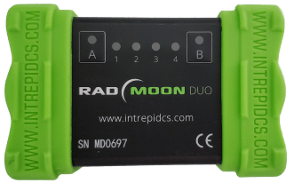
3.1.1. LED Indicators
Device Status/Configuration
LED |
Description |
LED State |
Mode |
A |
Script/Host Connection Status |
Orange |
Powered |
White |
USB Connected |
||
Blue/Green Flash |
Online with VSPY |
||
Magenta |
Script Running |
||
B |
AE1 Configuration |
Rapid Flash |
Media Converter Mode / AE1 connected to ETH1 |
Slow Flash |
Network Interface Mode / AE1 connected to host computer |
||
Off/Strobe |
Invalid Configuration |
Link Status/Mode
LED |
Port |
PHY |
Link Status |
Master/Slave Mode |
1 |
AE1 |
100BASE-T1 |
Flashing = Link Down Solid = Link up |
Cyan = Auto (Link Down) Green = Master Blue = Slave |
2 |
AE2 |
|||
3 |
ETH1 (Left) |
100BASE-TX |
Off = Link Down Solid Green = Link Up |
Auto |
4 |
ETH2 (Right) |
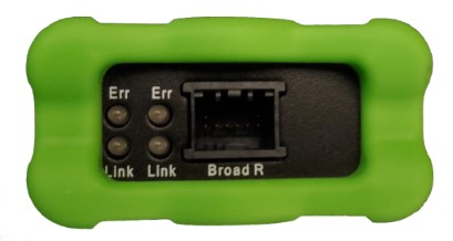
Endpanel LEDs
Green |
100BASE-T1 Link/Activity |
Red |
100BASE-T1 Error Status |
3.1.2. Membrane Buttons
Pressing the membrane buttons will cycle the 100BASE-T1 PHYs through auto/master/slave modes.
A |
Cycles PHY Mode for AE1 |
Cyan = Auto (Link Down) Green = Master Blue = Slave |
B |
Cycles PHY Mode for AE2 |
3.2. Connector Interfaces
3.2.1. 100BASE-TX / USB
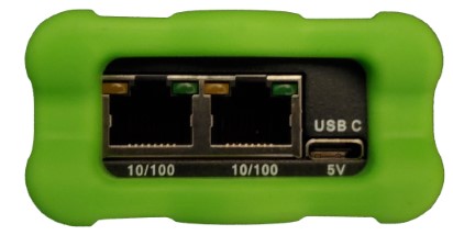
This side of the device has two standard RJ-45 jacks for the two 100BASE-TX ports.
ETH1 |
Left Connector |
ETH2 |
Right Connector |
The USB Type C connector provides power to the device as well as data connection to a host PC. If only powering the device is needed, a standard USB charger rated for 1A or more can be used.
Caution
Using a USB power source rated for less than 1A may cause the device to malfunction and possibly even damage it.