Figure 1 - The neoVI has three settings inside the box.
Hardware Settings - neoVI
Main
Applies to
neoVI Blue
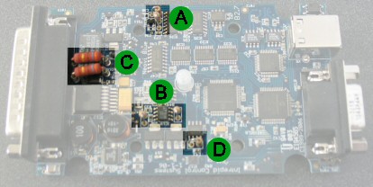
While most neoVI settings are software programmable a few are set with hardware. The following items are set in hardware: 1) the termination resistors for low speed fault tolerant CAN, 2) the pull up resistors for the UART/ISO/Keyword 2k network, 3) the J1850 PWM LBCC network, and 4) Lin Master Resistor. Table 1 and Figure 1 explain how to make these settings.
Table 1 - Hardware Settings in the neoVI device
| Setting |
Bubble in Figure 1 |
Instructions |
| Low Speed Fault Tolerant CAN Termination | A | Insert two 0.25 W resistors end to end in the sockets. See terminating a Low Speed Fault Tolerant CAN network for details. |
| K and L line pull-up resistors | B | Insert two 0.25 W resistors end to end with desired pull up values (510 Ohms are the factory default) |
| J1850 PWM LBCC | C | Insert two 0.5 W resistors end to end with the desired termination. (160 Ohms are the factory default) |
| LIN Master Resistor | D | Insert a 0.25 resistor end to end in the socket. This resistor is used as the master resistor. (510 ohms is the factory default) |
Figure 1 - The neoVI has three settings inside
the box.
| neoVI Documentation - (C) Copyright 2000-2020 Intrepid Control Systems, Inc. |
Last Update: Thursday, July 09, 2009