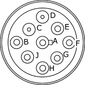
Figure 1 - The J1939-RP1210 Connector Vehicle End View
neoVI Yellow
Vehicle Side Connections
Main
Applies to
neoVI Yellow
The neoVI Yellow has a 15 pin Connection. This pin-out is in Table 1.
Note that the neoVI Yellow connector pin-out is also diagrammed on the bottom sticker of the device.
Table 1 - The neoVI Yellow 3 Connector Pin Descriptions
| Pin | Name | Description |
| 1 | TSYNC CLK H | TSYNC CLK H |
| 2 | TSYNC CLK L | TSYNC CLK L |
| 3 | ISO L | UART/ISO9141/Keyword Line "L" |
| 4 | MISC DIO 1 | Miscellaneous Signal 1 |
| 5 | J1939 2 H (CAN 2 H) / J1850 VPW | High Speed CAN High / J1850 VPW (Class 2) |
| 6 | GND | Electrical Ground |
| 7 | Shield | Shield |
| 8 | V BATT | Electrical Positive Supply 6-32 VDC |
| 9 | MISC DIO 2 | Miscellaneous Signal 2 |
| 10 | J1939 2 L (CAN 2 L) / ISO K | High Speed CAN Low / UART/ISO9141/Keyword Bi-directional Line "K" |
| 11 | MISC DIO 3 | Miscellaneous Signal 3 |
| 12 | J1939 1 L (CAN 1 L) | High Speed CAN Low |
| 13 | J1939 1 H (CAN 1 H) | High Speed CAN High |
| 14 | J1708 L(-) | J1708 Low |
| 15 | J1708 H(+) | J1708 High |
Figure 1 - The
J1939-RP1210 Connector Vehicle
End View
Table 2 - The neoVI Yellow J1939-RP1210 Connector Pin Description
| Deutsch Pin | Pin neoVI Yellow | Name |
| 1/A | 6 | Electrical Ground |
| 2/B | 8 | Electrical Positive Supply 6-32 VDC |
| 3/C | 13 | High Speed CAN High |
| 4/D | 12 | High Speed CAN Low |
| 5/E | 7 | Shield |
| 6/F | 15 | J1708 High |
| 7/G | 14 | J1708 Low |
| 8/H | 5 | High Speed CAN 2 High |
| 9/J | 10 | High Speed CAN 2 Low |
| neoVI Documentation - (C) Copyright 2000-2020 Intrepid Control Systems, Inc. |
Last Update: Thursday, July 09, 2009