3. A Tour of RAD-Moon3 Hardware
3.1. Label and Status Indicators
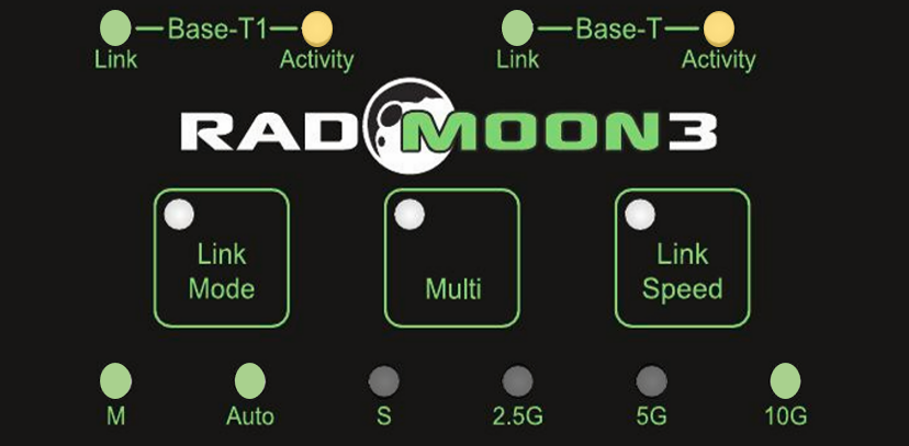
3.1.1. Link Status and Activity
Each PHY has its own Link and Activity indicators at the top of the label.
LED Status |
PHY Status |
|
Link |
Inactive |
No Link |
Solid Green |
Active Link |
|
Activity |
Inactive |
No communication |
Flashing Green |
The LED is active green for a brief time for each frame that is received. |
|
Flashing Amber |
When both activity LEDs are rapidly flashing amber, the RAD-Moon3 is one of the IEEE 802.3ch Test Modes |
|
Transient Red Flash |
The PHY has reported one of the following transient errors:
|
|
Periodic Red Flash |
A periodic red flash represents a fatal error where the RAD-Moon3 is not able to function. The number of flashes repeated in one period indicates the type of fatal error present.
These types of errors are not common and suggest the RAD-Moon3 may require service. Please contact Customer Support for assistance. |
note
If not using the auto mode, it is important to ensure that two PHYs are not configured identically (both M or both S), or a link will not be established.
3.1.2. Link Mode
When one PHY is linked with another, it uses a single clock between the two for synchronous data transmission and reception. There are 3 modes the PHY can assume regarding this clock. The current mode of operation is indicated with the left 3 LEDs in the bottom row of the label.
Pressing the  button will cycle through the 3 different link modes.
LED (Active Green) |
PHY Mode/Status |
|---|---|
M |
The PHY is supplying the clock signal |
S |
The PHY is receiving the clock signal |
Auto |
The PHY will detect the clock mode of other device and automatically be set to M or S accordingly |
Important
If not using the auto mode, it is important to ensure that two PHYs are not configured identically (both M or both S), or a link will not be established.
3.1.3. Link Speed
The link speed of the RAD-Moon3 is indicated with the right 3 LEDs in the bottom row of the label.
Pressing the  button will cycle through the 3 different link speeds.
BASE-T and BASE-T1 link speeds are identical.
The BASE-T PHY does not auto-negotiate link speed. Its link speed is statically set to match the BASE-T1 PHY.
Below are the minimum and maximum latencies at each link speed for minimum and maximum frame size.
Link Speed |
Frame Size (Bytes) |
Min Latency (µS) |
Max Latency (µS) |
2.5 Gbps |
64 |
5.8 |
6.2 |
1518 |
10.9 |
11.2 |
|
5 Gbps |
64 |
3.7 |
3.8 |
1518 |
6.5 |
6.6 |
|
10 Gbps |
64 |
2.7 |
2.7 |
1518 |
3.8 |
3.9 |
Note:
The settings described in this section can also be modified using neoVI Explorer or Intrepid’s open source cross-platform device communication API. (explained later in this guide)
3.1.4. SQI Indicators
Initial production of the RAD-Moon3 contains the 88Q4364 PHY, which does not support SQI as defined in IEEE 802.3ch. In the absence of an SQI value, the RAD-Moon3s containing this PHY indicate a calculation of signal-to-noise ratios when the link is established by activating the 4 LEDs on the side of the case according to the following table.
# Active Green LEDs |
Signal-to-noise Ratio |
1 |
SNR ≤ 21 |
2 |
22 ≤ SNR ≤ 23 |
3 |
24 ≤ SNR ≤ 25 |
4 |
SNR ≥ 26 |
RAD-Moon3 hardware containing the 88Q3244 (when available) indicate the Automotive Ethernet SQI (Signal Quality Index) as defined in 802.3ch using the using 4 multi-color LED’s on the side of the case. There are 12 discrete levels for the SQI which directly correlates to the BER reported by the PHY as it receives frames.
SQI Levels |
Indication |
|
|---|---|---|
Green |
9-12 |
Good (BER < 10E-20) |
Blue |
5-8 |
Acceptable |
Red |
1-4 |
Poor (BER > 10E-7) |
3.1.5. Bootloader Mode
You may see all the LEDs on the top label flashing synchronously with the 4 LED’s on each side of the case. This means the device is in bootloader mode, which should only happen when flashing the device’s firmware. If this is observed unexpectedly or following a firmware update, please contact customer support for assistance.
3.2. Connector Interfaces
3.2.1. Ethernet Interfaces
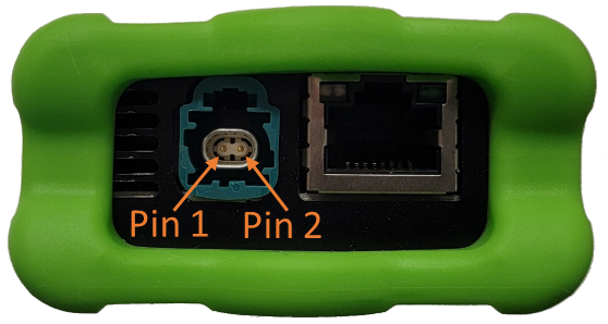
H-MTD Port (Left):
A connector designed specifically for MultiGBASE-T1 and Automotive Requirements.
H-MTD Connector Pinout |
||
Pin # |
Label |
Description |
1 |
TRD+ |
Data transmit and receive, positive |
2 |
TRD- |
Data transmit and receive, negative |
For the mating H-MTD connector Reference USCAR-EWCAP Drawing Number 777-U-002-1-Z01
Note
Polarity Auto-Detection and Auto-Correction are enabled by default on both PHYs of the RAD-Moon3.
Important
The manufacturing of reliable MultiGBASE-T1 cables is complex and requires specialized equipment to insure the electrical characteristics are met to achieve a stable link with acceptable SQI. Modifying these cables or attempting to assemble cables without the proper knowledge and equipment can often lead to problems with establishing a link between two devices.
RJ-45 Port (Right): An industry-standard conventional Ethernet jack.
Link LED (Green): Indicates that a valid link has been established between your device and another 10/100/1000 Ethernet device.
Activity LED (amber): Flashes when traffic passes in either direction over the attached Ethernet cable.
In normal operation you should see the Link LED always on, and the Activity LED flashing at a variable rate, with faster flashing meaning that more data is being transferred.
No link speed auto-negotiation
The link speed of this port is statically set to match the BASE-T1 PHY.
3.2.2. USB/Power Interfaces
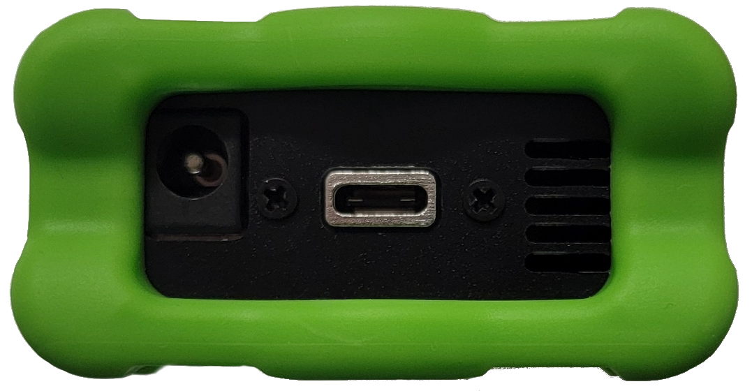
Barrel Jack (Left):
The device must be powered using a DC supply between 6-40V volts with a minimum power of 10 Watts. Using a power supply that does not meet these requirements may cause the device to malfunction or be permanently damaged.
USB Type C (Center):
This serves as a connection to a host computer for configuration, firmware updates, and PHY register access.
Voltage Supply Current Requirements
The RAD-Moon3 draws a nominal current of 500mA TO 600mA at 12 Volts. It is estimated that under worst cause conditions it could draw on the order of 750mA at 12V.
Voltage |
current |
|---|---|
12V |
750 mA |