6. Core Features
This section describes the specific features of the VividCAN and how to control them through Vehicle Spy. Two examples are provided showing how to use Vehicle Spy’s function blocks and Graphical Panels to create custom tools for the VividCAN.
The examples use Intrepid Control Systems’ Vehicle Spy. It is the tool for working with your VividCAN. Due to the complexity of Vehicle Spy, we only describe the basics necessary for the examples; for full details on this powerful software tool, please see the separate Vehicle Spy documentation.
6.1 Function Block Action: Display Characteristic Settings
Some VividCAN display settings can be set using Function Blocks. Use the “Set Value” function block action with the Expression Editor “Value” coming from “Misc”->VividCAN
- Backlight (0-100)
- Backlight is 0 – minimum
- 100 - maximum brightness
- Lock Touchscreen (0 or 1)
- 0 - not locked,
- 1 - locked which disables all user input to the touchscreen
- Show Panel (enumeration) – Gives control to show specific displays
- Main Menu = 0
- Graphical Panels = 1
- Log Data = 2
- Data Plot = 3
- Time & Date = 4
- Network Stats = 5
- About = 6
- Configuration = 7
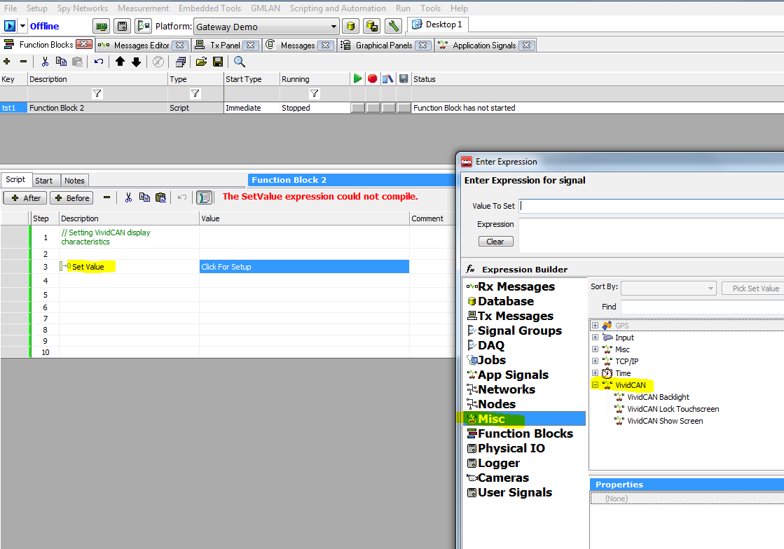
Display Characteristic Settings
6.2 Function Block Action: PWM Output
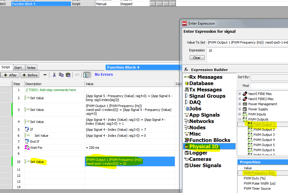
VividCAN supports one PWM output connected to a speaker/buzzer. Use the “Set Value” function block action with the Expression Editor “Value” coming from Physical I/O->PWM Outputs -> Output1. The “Value to Set” =PWM Output 1 (PWM Frequency (Hz)) :neo0-po0-1-index(0) and the “Expression” =.Frequency value (value of 10hz-8192hz, and 0 to silence)
- For example: {PWM Output 1 (PWM Frequency (Hz)) :neo0-po0-1-index(0)} = 10. This function block action will play a 10Hz tone from the VividCAN speaker.
PWM Output
6.3 Function Block Action for “Log Data”
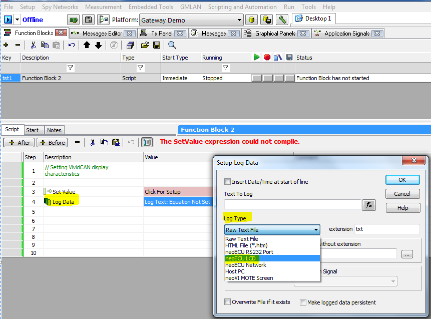
VividCAN supports Function Block Action “Log Data” with Log Type set to “neoECU LCD” This is used to display strings on the Log Data display, up to 32 separate strings.
Strings can be static or hold data/application signals.
Choose the line number (0-31) to display on the “Log Data” display.
Commas can be used to separate strings on the same line. For example:
- Label name = Buttons; Application signal = Button State (Value) :sig0-0
- LogData -> Buttons:,{ Button State (Value) :sig0-0}
- Label (“Buttons:”) will left-justify, the Application Signal (Button State (Value) :sig0-0) will right-justify on the screen
Log Data
6.4 VividCAN supports VSpy Graphical Panels”
Ported through CoreMini - only the functionality listed below:
Up to 16 panel pages
Up to 64 controls per panel page
Controls will only compile to VividCAN if the associated signal is present in the CoreMini
Controls without a signal will not show up on VividCAN, except text and graphics
Supports these Graphical Panel controls:
- Text, LED, Bargraph, Meter, FBlock Button (Start, Start/Stop), Tx Button, On/Off Button, Graphical Display and Bitmap Button
Supports the Graphical Panel page background color, and each control color
Does not apply any border styles to individual controls, only basic look and position
- basic border style only will be added in future Vsp3 software
All strings are limited to 31 characters
Graphical Panel “Grid” tab provides VividCAN screen grid template check box
- If checked VividCAN grid template and tool set is displayed
- This helps to show how much space there is for Graphical Panels on VividCAN’s screen
Update Rate is set to max 60 Hz on VividCAN, does not port value from VSpy
Size of each panel page is 410 wide x 236 tall
You can overlap controls for a more custom look
Setup a signal for each control:
- Each control can have its own Signal or Expression
- It can be an equation, a single Application Signal or message signal, or a static value
6.5 Full Screen Mode
The Graphical Panel pages on VividCAN has a default pixel resolution of 414 x 238. There is space reserved for the top menu bar and the right side status bar. Full Screen Mode allows the Graphical Panel pages to be displayed using the full screen resolution of 480 x 272 - giving more screen real-estate for additional content on each page. Full screen mode is only allowed if CoreMini is running and displaying a Graphical Panel page. There are two ways to enter Full Screen Mode.
- Pressing the Full Screen Mode button on the right side of the screen.
- Performing a pinch-to-zoom gesture in the Graphical Panel page.
To exit Full Screen Mode , perform the reverse pinch-to-zoom gesture.
Note: While in Full Screen Mode, Graphical Panel scrolling arrows are hidden. To scroll, another gesture is available. To do this, touch the screen with two fingers and slide them both across the screen from left-to-right or from right-to- left. This will only work if there are multiple pages in your VividCAN Graphical Panel setup.
6.6 VividCAN J1979 Support
A custom Vspy3 script is available from Intrepid Support. “J1979 HS CAN Example 2.vs3’
Includes:
- 12 function block scripts
- Graphical Panel setup to start all function blocks
- Function blocks request a series of PIDs on the HSCAN network, show the responses in Graphical Panels
6.7 VividCAN Settings
VividCAN saves the following settings that load on power up:
- Screen brightness, last viewed page, theme, time zone
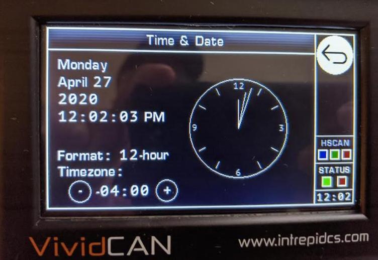
- Time zone can be adjusted from the Time & Date display page, 12/24-hour mode (This only affects the time shown on VividCAN screen)
6.8 VividCAN Numeric Character Types (integer, Double Float)
- VividCAN Graphical Panels use 32-bit signed integer values for tool type “”bar graph”, “Meter”, and “LED” controls, while VSpy uses double values. This can lead to display differences between VividCAN and Vehicle Spy. This will affect - min and max values for bargraph, meter, and LED controls. Note: calculated values have min and max values from -2,147,483,648 to 2,147,483,647.
6.9 VividCAN Character Fonts
- Font sizes supported are 12, 16, 20, and 24, other sizes will round up to these sizes
- VividCAN supports 16-bit color while Vehicle Spy supports 24-bit color which may affect the results of your VividCAN display color design.
6.10 VividCAN Supported Vspy3 Scripting Commands
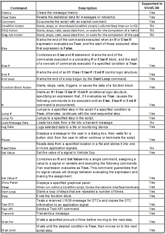
Log Data
6.11 Display Main Menu
The “Main Menu” is displayed when connected and powered by the Micro USB to PC cable or the return to “Main Menu” icon is pressed. The displayed options/functions can be selected by touching the VividCAN’s touch screen. The “Main Menu” displays the following options/functions pages:
- Graphical Panels. The “Graphical Panels” page when selected, displays the Vehicle Spy graphical panels downloaded into the VividCAN. When connecting the VividCAN with the DB-9F to OBDII cable, the Graphical Panel view is defaulted. Details on how to create and download graphical panels are covered in the examples section. Up to 16 Graphical Panels, each with up to 64 controls (subject to change and limited to overall 64 kB CoreMini size)
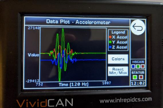
- Accelerometer. The “Accelerometer Page” when selected, displays the output of the internal triaxial accelerometer. This is a “display only” page, this data is currently not stored or transmitted to either the PC or CAN network.
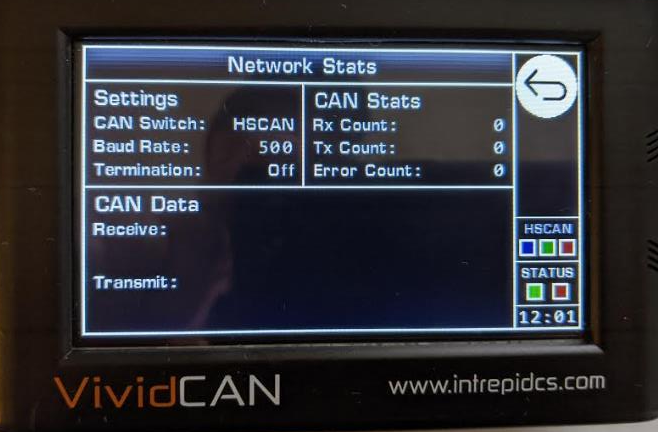
- Network Stats. The “Network Status” page when selected displays the CAN settings, CAN stats (Rx count, Tx count, Error Count) and CAN data frames transmitted and received.
- Log Data. The “Log Data” page when selected, displays Vehicle Spy’s Function Block: Log Data parameters. Details on how to create and download Log Data are covered in the setup example section Example2. The VividCAN is not a data logger. Data is only displayed in this mode.
- Time & Date. The “Date & Time” page when selected, displays the VividCAN’s current real time clock. The VividCAN time and date can be set from this page.
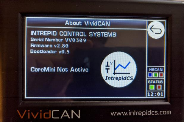
- About. The “About” page when selected, displays the current firmware loaded in the VividCAN.
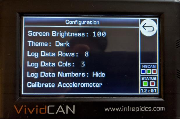
 Setup Configuration. Allows the user to set screen display characteristics, Log data screen partitions and re-calibration of the internal tri-axial accelerometer. Making changes to the Setup page will be saved when the “Return to Main Menu” icon is pressed.
 CAN Switch. The CAN switch display shows the current CAN network selected, CAN traffic status and current time.
 Return to Main Menu
 Graphical Panel selection arrows. Pressing “>” scrolls to the right, pressing “<” scrolls to the left.
6.1. VividCAN Programming Examples
Example1: Add Meter widget and text
The most basic use of the VividCAN is to add “Graphical Panels” to display vehicle or bench signals. In this first example a “Graphical Panel “Meter” widget along with “Text Entry” to identify the signal the “Meter” is representing will be setup
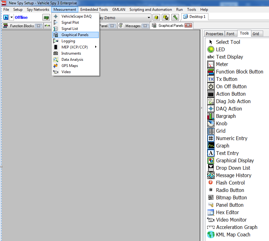
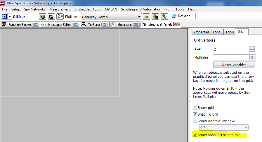
- To get started, connect the VividCAN to the PC via the MicroUSB to PC cable, and open Vehicle Spy and select Measurement ->Graphical Panels.
- Open the “Grid” tab on the right side of the “Graphical Panels” page. Locate and check the option box titled “Show VividCAN screen size”. Selecting this box sets the “Graphical Panels” tool set and shows a grid that represents the VividCAN display size. Keeping all widgets and text within this grid assures proper placement on the VividCAN display.
- Open the “Tools” tab on the right side of the “Graphical Panels” page to view the VividCAN’s tool set.
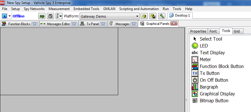
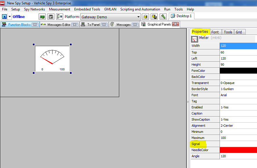
- Left click on the “Meter” tool (you do not need to hold the mouse button), mouse over to the VividCAN grid and right or left click to drop a meter widget into the VividCAN grid. At this point the “Meter” is selected (4 dots surrounding the “Meter”).
- Move back to the right side of the “Graphical Panels” and select the Properties tab. This tab displays the properties associated with the “Meter” widget. The “Meter” “Signal” property allows connection to a received, transmitted or application signal value.
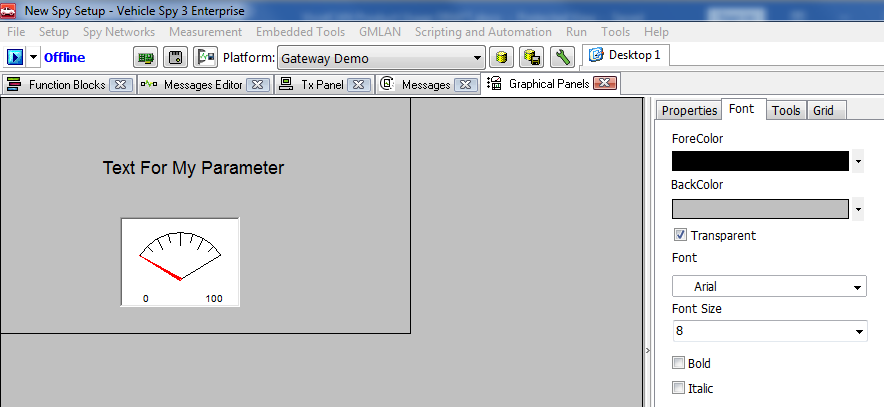
- Next, let’s add text to describe the signal being displayed by the “Meter” widget. Again, go to the “Tools” tab and left click on the “Text Display”. Move the mouse pointer to the location for the text – right or left click to set the text (the “Text Display” is selected, indicated by the four dots). Open the properties tab and setup the properties for the “Text Display”. You can open the “Font” tab to setup font color, type and size.
Note
Note: Not all font types and sizes are supported in the VividCAN. See section 5.8 for types and sizes supported.
The tool design/script is done, and it needs to be sent to the VividCAN. The Coremini console will be used to compile and download the design to the VividCAN. From the main Vehicle Spy tabs, open Tools- >CoreMini Console. Clicking on the CoreMini Console option starts the error checking and compiling of the design/script. The CoreMini Executable Generator window opens when complete. Check for errors in the “Build” tab. At this point the design/script is ready to be downloaded to the VividCAN. Verify that the “Target Device” lists the VividCAN connected to the PC Clicking on the “Send” button will send the design/script to the VIvidCAN. When the download is complete the VividCAN will run the design/script (Figure 17).
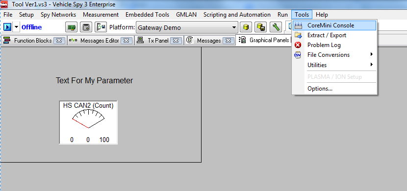
Figure17
Note
Note: The VividCAN’s CoreMini will not run with a MicroUSB to PC cable connected following a power cycle after the initial download. Connecting a DB-9F to OBD-II or MicroUSB to PC without a data connection (power only) is required.
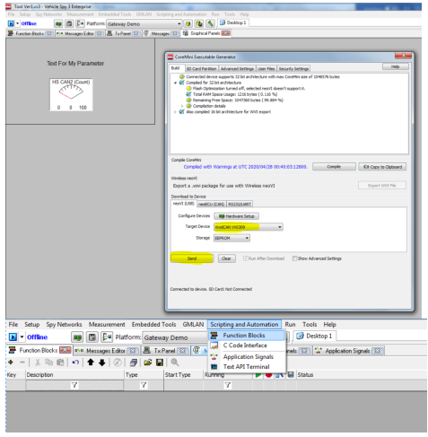

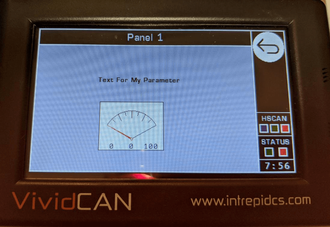
Figure18: VividCAN Running Design/Sript
Example2: Add signals to Log Data display window
A function Block script is needed to add signals to the Log Data display window. The Function Block Action “Log Data“ with the Expression “Value” equals to the Receive Message, Transmit, Application or Text signal to be displayed.
- To get started, connect the VividCAN to the PC via the MicroUSB to PC cable, and open Vehicle Spy and select Scripting and Automation ->Function Blocks
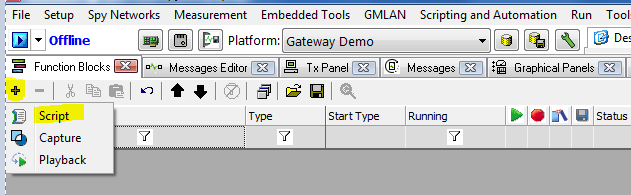
- Click on the “+” icon in the Function Block page. A drop-down will open with three choices, select Script.
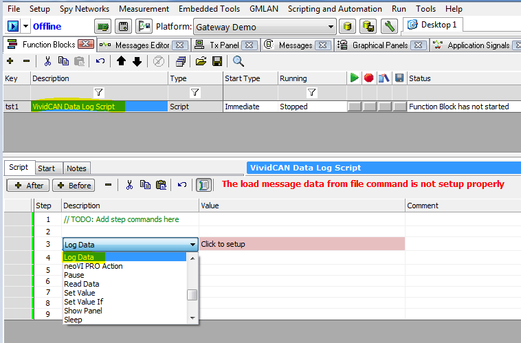
- Selecting “Script” opens Vspy’s Function Block scripting editor. Double click in the second row of the Description column to open a script command window. This window contains all the Vspy scripting commands. Locate the “Log Data” command and click on it.
(Hint: there is a “first letter only” search command within the script command window. Typing the first letter locates the commands with the first letter selected. Type “L” to locate all commands that start with “L” – i.e. Log Data).
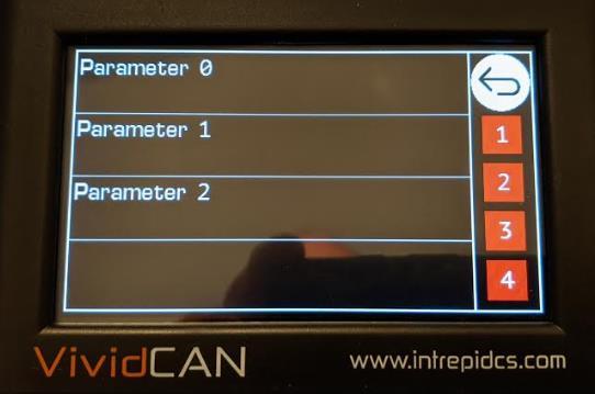
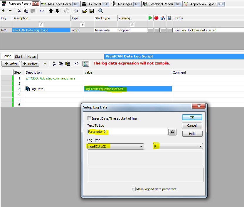
- The “Log Data” command is now selected. Click in the “Value” column to select what is going to be displayed in the VividCAN’s Log Data display. In this example, the text “Parameter 0” and “Parameter 1” will be displayed in the Log Data display. Enter the text in the “Text to Log” field or select the Fx to open the Expression Editor to enter Receive, Transmit, or Application signls.
- Select the “Log Type” to neoECU LCD
- Enter the Log Data display position number associated with this value. In this example “Parameter 0” will be placed into position 0
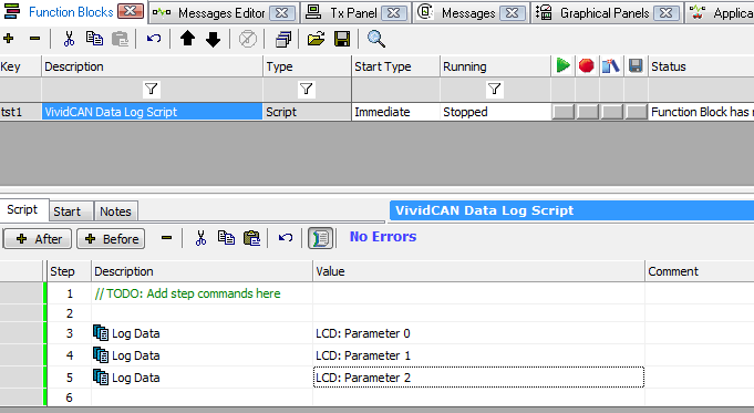
- Follow the same procedure for additional signals/parameters to be displayed. Note to increment the parameter position number.
- The tool design/script is done, and it needs to be sent to the VividCAN. The Coremini console will be used to compile and download the design to the VividCAN. From the main Vehicle Spy tabs, open Tools- >CoreMini Console. Clicking on the CoreMini Console option starts the error checking and compiling of the design/script. The CoreMini Executable Generator window opens when complete. Check for errors in the “Build” tab. At this point the design/script is ready to be downloaded to the VividCAN. Verify that the “Target Device” lists the VividCAN connected to the PC Clicking on the “Send” button will send the design/script to the VIvidCAN. When the download is complete the VividCAN will run the design/script.