3. A Tour of neoECU AVB/TSN Hardware
Before learning how to configure and set up the device, let’s examine the device from all sides to understand all of its interfaces and status indicators.
3.1. Label and Status Indicators
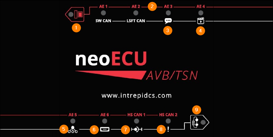
1 |
Red Button (Activates Red Labels) |
Solid Blue: Red LED labels apply |
Inactive: Unpowered, booting, or White Button is active |
||
2 |
AE1-6 (100BASE-T1) |
Solid Blue: Link Active |
Inactive: No Link |
||
3 |
Text Balloon |
Solid Blue: Talker configuration |
Inactive: Listener Configuration |
||
4 |
Clacker |
Solid Blue: Configured as video endpoint |
Inactive: Not configured as video endpoint |
||
5 |
GM Indicator |
Red: Standard Profile / No AS-Capable Device Connected |
Solid Blue: Grand Master |
||
Flashing Blue: Clock Slave |
||
6 |
HDMI |
Solid Blue: Configured for HDMI output |
Inactive: Currently an invalid state |
||
7 |
Stream Status |
Solid Blue: Stream Active |
Inactive: No Stream Active |
||
8 |
Device Error |
Solid Red: Internal Software Fault Detected |
Inactive: No faults detected |
||
9 |
White Button Activates Red Labels Toggles status screen on HDMI |
Solid Blue: White LED labels apply |
Inactive: Unpowered, booting, or Red Button is active |
3.2. Connector Interfaces
3.2.1. Ethernet / Audio Endpanel
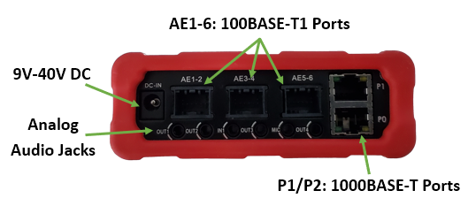
DC In
This device is shipped with a 12V DC power supply which mates with this connector. DC supplies with a compatible connector can be used provided they supply a voltage in the range 9-40 Volts with a current of 1A or greater.
Audio Ports
If enabled, OUT1-4 provide an unamplified signal of the audio being streamed for use with headphones or external amplifier. This audio is present for both talker and listener endpoint configurations.
Audio Port |
Audio Channel |
Notes |
Out1 |
1/2 |
2-Channel Audio from Video Stream |
Out2 |
3/4 |
|
Out3 |
5/6 |
|
Out4 |
7/8 |
Channel 8 is the “.1” if the stream is Dolby 7.1 |
IN1 |
Can be configured as source for audio talker stream |
|
MIC |
Not used |
Note
Stream 0 is the only stream associated with these audio ports. Additional audio streams can be connected simultaneously but this device is not capable of decoding and playing the audio.
Ethernet Ports
The following diagram helps visualize the different modes of operation that are configurable in the neoVI Explorer configuration utility. It also shows the physical port assignments on the 88Q5050 which must be known to configure the switch properly for your network.
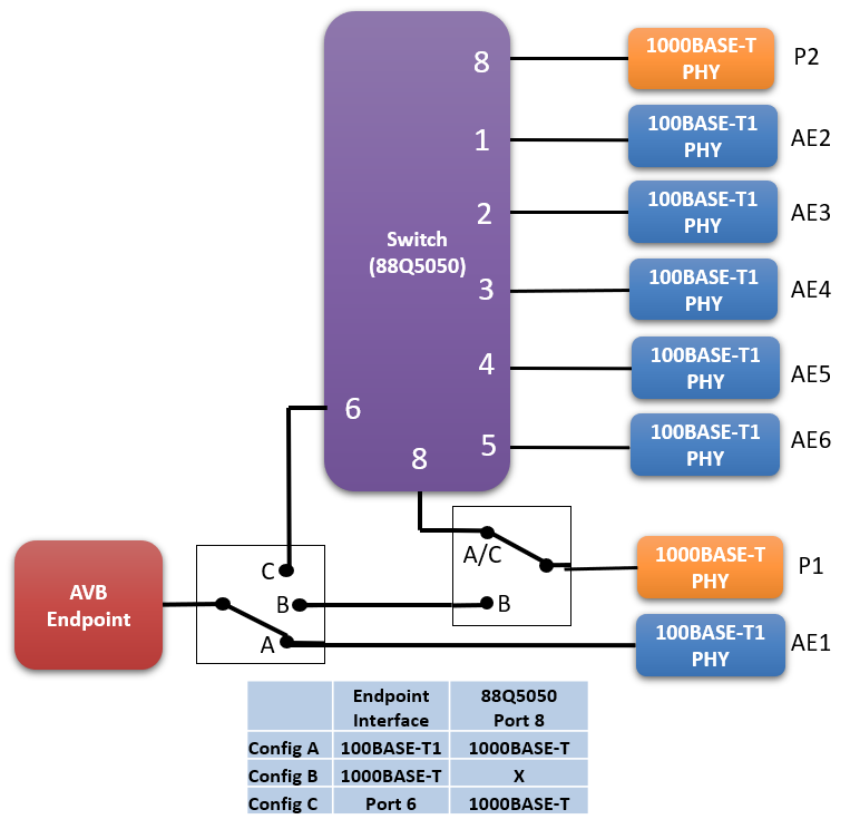
The AVB Endpoint PHY is selectable between AE1 (100BASE-T1) and P1 (1000BASE-T) |
The 5x 88Q5050 100BASE-T1 Ports are connected to AE2-6:
The 1x 88Q5050 1000BASE-T Port is connected to P2
3.2.2. USB / HDMI / CAN Endpanel
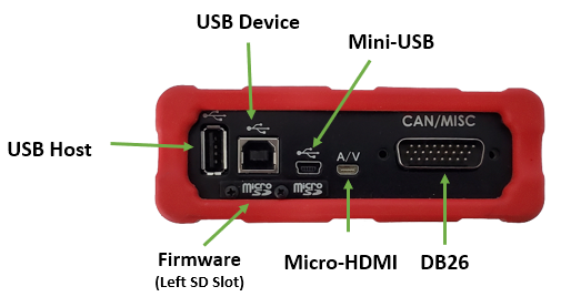
USB Host
This port can be configured to be the source of a video stream using a Linux compatible web cam.
USB Device
This port is used to connect to a PC for configuration or to utilize the CAN/LIN interfaces.
Mini-USB
This interface is not used.
Micro SDCard Slots
The firmware and media storage resides on micro SDCards in these slots. The data on this media is not intended to be accessed or updated with anything other than Intrepid software. Not using Intrepid software with this media may render the device inoperable and void the warranty of the device.
Micro-HDMI
his interface can be connected to an display to the video being streamed by a talker or received by a listener.
DB26
Reference pin assignments in the following section.
3.2.3. Connector Information
DB26 (Power/HSCAN)
Pin |
Signal |
4 |
HSCAN 1 L |
6 |
HSCAN 2 L |
10 |
GND |
14 |
HSCAN 1 H |
16 |
HSCAN 2 H |
19 |
VBATT |
100BASE-T1 Connections (AE1-6)
Ports |
100BASE-T1_P |
100BASE-T1_N |
|---|---|---|
AE2 / AE4 / AE6 |
Pin 8 |
Pin 7 |
AE1 / AE3 / AE5 |
Pin 4 |
Pin 3 |
3.2.4. AVB Endpoint Status Screens
When the micro HDMI port is connected to a display, a video overlay displaying endpoint status information can be enabled by double pressing the white switch membrane on the top label of the device.
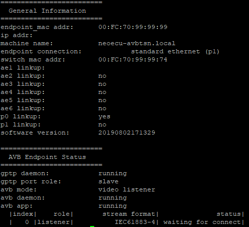
Absence of IP Address
Note that AVB/TSN is a set of Layer 2 protocols, therefore an IP Address is not necessary, and may not be present.
Stream Status lists all streams which have been enabled in the configuration, their format, and connection status.
Helpful Debug Information
Anything “Stopped” suggests a problem with the device’s software or device configuration
If gPTP port role status is “disabled”, it is waiting to be connected to an asCapable device