5. The neoVI Explorer Configuration Utility
5.1. Starting and Using neoVI Explorer
The neoVI Explorer utility allows you to connect to, manage and configure all of your Intrepid Control Systems hardware. It is supplied both as an integrated feature of Vehicle Spy, and as a standalone program. This section will describe general features and the basics of using neoVI Explorer, so you will understand the utility when we get into settings specific to your device.
5.1.1. Starting neoVI Explorer from within Vehicle Spy
There are several ways to open neoVI Explorer from within VSpy. These are probably the two easiest, since they are accessible at all times:
Menu Item: Click the Setup menu and then select Hardware.
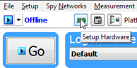
Hardware Setup Button: Click the button located in the main Vehicle Spy toolbar just under its menu (Figure below).
Note
neoVI Explorer cannot be launched when Vehicle Spy is online (even if in simulation mode). If you attempt to do so, VSpy will prompt you to either go offline and launch neoVI Explorer, or remain online and return to Vehicle Spy.
5.1.2. Starting neoVI Explorer as a Standalone Program
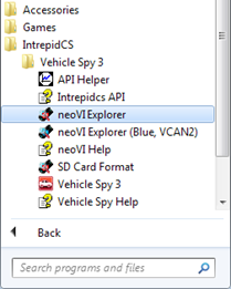
If you want to work with your device without opening Vehicle Spy, you can launch neoVI Explorer directly. Open the Start Menu, navigate to the IntrepidCS folder, then under the Vehicle Spy 3 sub-folder, select neoVI Explorer (Figure below).
5.1.3. Starting neoVI Explorer as a Standalone Program (API Kit Installed)
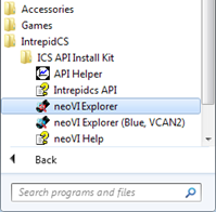
If you installed the API kit and support files instead of Vehicle Spy, you can run neoVI Explorer from the Start Menu using the same basic process as described above. The only difference is the name of the sub-folder, so you will navigate to the IntrepidCS folder, then open the ICS API Install Kit sub-folder, and finally select neoVI Explorer (Figure below).
5.2. Interfacing with your device
5.2.1. Connecting to your device
When neoVI Explorer loads, it will start up with the first hardware device it can find selected in the menu pane on the left. You should see your device listed here, along with its serial number. If you don’t see the device to be connected, but do see other Intrepid devices, be sure to scroll down to look for it. If it is still not visible, this means its drivers have not been installed correctly, it is not powered properly, or there is a problem with the USB connection.
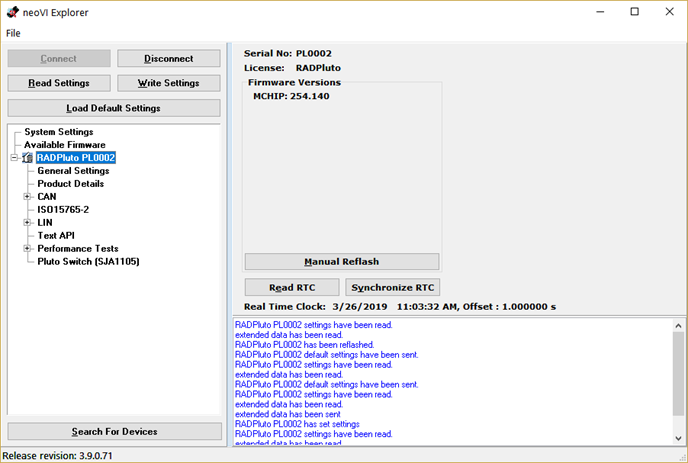
To manage your device, click on its entry in the navigation pane (if it is not already highlighted) and then press the Connect button. After successfully connecting to the device, you will see a “thumbs up” icon next to the device’s name, and checkmarks will appear next to currently-enabled networks in the explorer area on the left. You should also see a message in the message box on the right saying “<Your Device and Serial Number> settings have been read”. This tells you that neoVI Explorer has loaded the current settings from the unit.
The screen as a whole should appear similar to the screen shown below (but note that the device and version number shown below may be different).
Searching for Devices
If you attach new hardware to your PC after starting neoVI Explorer, press the Search For Devices button at the bottom left of the dialog box to prompt the program to scan for new hardware you can manage.
Note
It is possible to click on various parameter groups at any time, but they will not show valid date until you connect to the device. Remember also to connect to the device before making changes, or they will be erased when you do connect to the settings in the hardware are
5.2.2. Device Configuration
Writing and Reloading Settings
To avoid potential problems, neoVI Explorer will not save any changes to device parameters until you instruct it to do so. This is done by pressing the Write Settings button, which will update the parameters within the firmware in your device. If you make changes you do not want to keep, pressing the Read Settings button will reload the settings stored in the device, wiping out any modifications made in neoVI Explorer that had not yet been saved.
Reloading Device Defaults
To return all settings to factory defaults, press the Load Default Settings button. This is convenient if many changes have been made and written to the firmware in the past, and you want to start over with a clean slate. Note that pressing this button actually writes the defaults to the device first, and then reloads them automatically, so you do not need to also press Write Settings. You will see messages in the message area telling you that defaults have been sent to the device and then read from it.
Disconnecting from the device
Press the Disconnect button to tell neoVI Explorer that you are done working with the device. This step is actually optional, because neoVI Explorer will disconnect from any connected devices when you exit the program.
Exiting neoVI Explorer
Like any Windows program, you can close neoVI Explorer by clicking the “X” in the top right corner, or pressing the Alt+F4 key combination.
5.3. System Settings and Firmware Updates
The top two entries in the explorer window on the left side of neoVI Explorer contain system- wide settings that apply to all hardware devices, and information related to firmware updates.
5.3.1. System Settings
In the top branch of the tree in the left pane of neoVI Explorer you will see several settings that you can enable or disable:
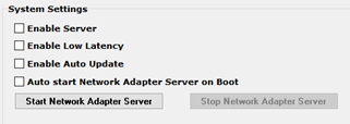
Enable Server: Turns on the neoVI Server feature, a background program that allows your hardware to be used by multiple applications at the same time.
Enable Low Latency: This is an advanced setting for applications where fast response is needed after transmission.
Enable Auto Update: When enabled, both neoVI Explorer and Vehicle Spy will automatically update firmware. If this box is not checked, firmware must be updated manually. (See below for details.)
Network Adapter Server: This is a feature that is used with Intrepid products having Ethernet ports. (It may not apply to your device.) With This feature enabled, the Ethernet ports on your Intrepid hardware will enumerate as network interfaces in the operating system of your host computer. This server can be started and stopped in this window. There is also a checkbox to configure the server to start after booting your computer.
5.3.2. Available Firmware
This is an informational page that shows which firmware versions are available in this version of neoVI Explorer for various Intrepid products. Note that some devices have multiple firmware programs that control different aspects of their operation; You normally won’t need to look in this area, because as we’ll see in Section , neoVI Explorer shows you the current and available firmware versions for your device when you connect to it.
5.3.3. Automatic and Manual Firmware Updates
Warning
While your device may appear to operate with incompatible firmware, proper and reliable operation cannot be guaranteed unless the version of firmware matches what is listed in Vehicle Spy
Firmware is essentially software that runs hardware and is required to enable the many capabilities of your device. New versions of firmware are created regularly by Intrepid’s engineers to implement new features and correct problems that have been identified.
If you have Enable Auto Update on—which is the default, and is recommended—then you don’t really need to worry about firmware updates. Each time you connect to your device in neoVI Explorer or go online with it in Vehicle Spy, the firmware will be checked, and if a newer version is available, the device will immediately be updated. If you do not have automatic updates enabled, you control when your firmware is updated. When new firmware is available, you will be notified on the initial connection screen, as shown below. Simply press the Manual Reflash button to update the firmware.
5.3.4. The Firmware Update Process
During the firmware update process, the device will be placed into bootloader mode, indicated by all LEDs on the top label flashing synchronously. Normal LED flash patterns will resume when the update is complete and the device reboots. You will see a dialog box on the screen showing you the progress of the firmware update operation. an example is shown below. You will also see messages in the message box on the right side of neoVI Explorer as the firmware program is sent to the device. When the process is complete the dialog box will disappear and another message will appear in neoVI Explorer to confirm that the update has finished. If you receive any error messages or experience any other problems updating your device’s firmware, please contact Intrepid for assistance.
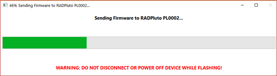
Warning
Please take heed of the warning on the firmware update dialog box: leave the device connected and powered on for the entire firmware update process to avoid possible problems with the device.
5.4. General Settings and Product Details
These two areas of the device’s parameter setup provide information about the device and allow you to perform a few basic maintenance tasks.
5.4.1. General Settings
After connecting to the device you will see basic information about it in the right-hand pane of the window:
The device’s serial number.
The firmware versions currently in the device, and an indication if new firmware is available.
A message showing that the hardware license for the device was recognized.
A current readout of the device’s real-time clock.
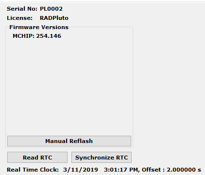
This information can be displayed again at any time by clicking the device’s name in the explorer navigation window, or the General Settings entry immediately below it.
The version(s) of the firmware for the device will be shown in black if it matches the firmware version within neoVI Explorer. If not, the current version and the newest available version will be shown in red to help you notice that an update is available. (See the previous section for more about the update process.)
There are three buttons on this screen.
Manual Reflash (described in the previous section)
Read RTC button will reload the device’s internal time clock
Synchronize RTC will set the device’s clock to the same value as that of the PC.
5.4.2. Product Details
This is an informational area that provides technical data on the devices’s hardware and internal setup. You will generally only need this if requested by Intrepid in order to facilitate support or troubleshooting. You can use the Copy To Clipboard button to copy all of the information to the Windows Clipboard, so you can then paste it into an email or file.
5.5. CAN Network Settings
5.5.1. CAN Networks
This area of neoVI Explorer is used to enable, disable and configure the High Speed CAN channels. Each channel has an entry under the “CAN” group (which cannot be clicked itself). The current status of each channel is shown next to its name; a green checkmark indicates that the channel is enabled, while a red X means it is disabled. The figure below shows an example of the CAN channels area, with HS CAN enabled and HS CAN2 disabled.

All of the CAN channels have the same parameters, which can be configured using the controls in the right-hand pane; the default settings are shown below.
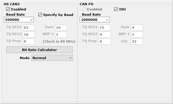
Enabled: Place a checkmark in this box to enable the channel, or clear the checkmark to disable it. When disabled, all of the other parameter controls are disabled (grayed out).
Specify by Baud: This is a master control that determines whether the operation of the channel is controlled by a numeric baud rate, or is calculated from lower-level timing parameters. When checked, the Baud Rate and CAN FD Baud Rate drop-down boxes are enabled and the various TQ, Sync and BRP-1 entries are disabled. When unchecked, this is reversed. Specifying by baud rate is the default, and is recommended except for advanced users with special requirements.
Baud Rate: When Specify by Baud is selected, choose a baud rate for the channel from the drop-down box below. The default value is 500000.
CAN Timing Settings: When Specify by Baud is deselected, the operation of the CAN channel is based on these five settings: TQ SEG1, TQ SEG2, TQ Prop, Sync, BRP-1. These settings are for advanced users and normally should be left at their default values.
CAN FD Baud Rate: When Specify by Baud is selected, choose a baud rate for the data phase of CAN FD messages. The default value is 2000000.
CAN FD Timing Settings: When Specify by Baud is deselected, use these settings (TQ SEG1, TQ SEG2, TQ Prop, Sync, BRP-1) for the data phase of CAN FD messages. These parameters are for advanced users and normally should be left at their default values.
Mode: The operating mode of the channel; choose from one of these four options: * Normal: Normal operation (default). * Disable: Channel is disabled. * Listen Only: This channel only receives messages, with no transmissions, and also no error frames generated nor acknowledgments sent.
Bit Rate Calculator: Press this button to launch the Intrepid Bit Timing Calculator.
5.5.2. ISO15765-2:
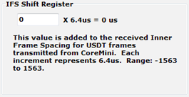
This page contains one setting: IFS Shift Register (shown below). Changing this from its default value of 0 causes time to be added to the Inner Frame Spacing of USDT frames transmitted by CoreMini scripts running in the FIRE 2. The number entered is multiplied by 6.4 µs to determine the time offset. The allowed range is -1563 to 1563.
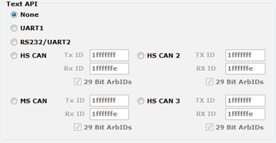
5.6. Text API
These parameters control the operation of the text API that can be used to operate the neoVI FIRE 2 using third party software. Please contact Intrepid if you require assistance with using the API.
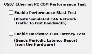
5.7. Performance Tests
The following are tests which can be used to characterize the bandwidth and latency between ICS hardware and its host computer. If you suspect you have a problem with either of these, our customer support would be happy to help resolve it. Reference the end of this document for contact information.
5.8. neoECU AVB/TSN Endpoint Configuration
The Endpoint can be configured in one of 3 modes from the dropdown menu displayed below.
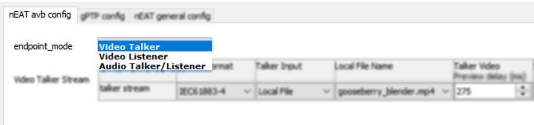
5.8.1. Video Talker Configuration: Source of an AVTP Video Stream
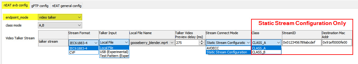
Stream Format: The AVTP video formats IEC61883-4 and CVF are supported and can be chosen from this drop down menu.
Talker Input: Any one of the following can be chosen to be the source of the video stream.
Local File:
Stream a media file stored in the devices internal storage.
Reference section 4.7.6 for media file management
USB:
Stream a video from a USB camera connected to the USB Host port.
Most cameras having a Linux driver will work.
Limited to resolution of TBD
Test Pattern
Local File Name: A list of available files will be displayed if Local File is selected as the Talker Input.
Talker Video Preview Delay (mS): Set the amount of time the video rendering will be delayed.
Stream Connect Mode
AVDECC: Endpoint will wait for an AVDECC command to connect with a Listener Endpoint.
Static Stream Configuration:
Stream Reservation Class, Stream ID and Destination MAC Address are statically configured instead of using MSRP.
Note that the endpoints still require MSRP to be supported by switches in the network.
Note
The following 3 configurations only applies to Static Stream Configuration
Class: Select Stream Reservation Class A or B.
StreamID: AVTP Stream ID
Destination MAC Address: The Destination Address used by the AVTP frame.
5.8.2. Video Listener Configuration: Sink of an AVTP Audio Stream
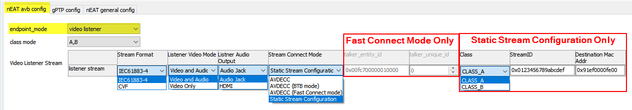
AVTP Stream Format: Select between IEC61883-4 and Compressed Video Format (CVF)
Listener Video Mode: Select between Audio/Video or Video Only
Listener Audio Output: Select between audio playing on Audio Jack #1 or over HDMI.
Stream Connect Mode
AVDECC: Endpoint will wait for an AVDECC command to connect with a Talker Endpoint.
Static Stream Configuration: Stream Reservation Class, Stream ID and Destination MAC Address are statically configured instead of using MSRP.
Note
The following 3 configurations only applies to Static Stream Configuration
Class: Select Stream Reservation Class A or B.
StreamID: AVTP Stream ID
Destination MAC Address: The Destination Address used by the AVTP frame.
5.8.3. Audio Talker/Listener Configuration: Simultaneous Source and Sink AVTP Audio Streams
Maximum Simultaneous Streams
Note: An endpoint is limited to a maximum of 9 simultaneous streams
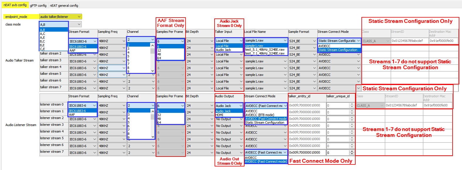
Audio Talker Stream
Stream Format: The AVTP video formats IEC61883-6 and AAF are supported and can be chosen from this drop down menu.
Sampling Frequency: of the audio stream
Channel: Number of audio channels in the stream
Samples per frame: Number of audio samples per AVTP Frame (AAF format only)
Bit Depth: of the audio stream
Talker Input: For Stream 0, the audio can be selected from either a file or an audio source connected to IN1. All other streams are from a local file stored on the endpoint.
Local File Name: Select the audio file from a list of files available.
Sample Format: This device requires S24_BE
Stream Connect Mode:
AVDECC: Endpoint will wait for an AVDECC command to connect with a Listener Endpoint.
Static Stream Configuration: Stream Reservation Class, Stream ID and Destination MAC Address are statically configured instead of using MSRP.
Audio Listener Stream
Stream Format: The AVTP video formats IEC61883-6 and AAF are supported and can be chosen from this drop down menu.
Sampling Frequency: of the audio stream
Channel: Number of audio channels in the stream
Samples per frame: Number of audio samples per AVTP Frame (AAF format only)
Bit Depth: of the audio stream
Audio Output: Note that only Stream 0 is decoded for listening and can be streamed out of OUT1 or over HDMI. The remaining streams are intended for testing only.
Stream Connect Mode
AVDECC: Endpoint will wait for an AVDECC command to connect with a Listener Endpoint.
Static Stream Configuration: Stream Reservation Class, Stream ID and Destination MAC Address are statically configured instead of using MSRP.
Note
The following 2 configurations only apply to Fast Connect Mode
Talker Entity ID: In Fast Connect Mode, the Listener will use AVDECC commands to attempt to connect a stream with a talking having this Entity ID.
Talker Unique ID (UID): UID of the Talker which the Listener will attempt to Fast Connect.
Note
The following 3 configurations only apply to Static Stream Configuration
Stream Class: Choose the Stream Reservation Class of the stream
StreamID: AVTP Stream ID
Destination MAC Address: The Destination Address used by the AVTP frame.
5.8.4. gPTP Configuration
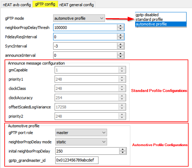
gPTP can be disabled, or set to the standard or Automotive Profile (AVNU)
Profile Independent Settings
neighborPropDelayThresh (nanoseconds)
Device will be identified as non-AS Capable if pDelay exceeds this value
Default 800, but increased to 100000 to insure latency of active tap does not impact ability to connect stream.
Can be set as high as 10000000 for the purposes of certain AVNU testing
Note
The value of the following 3 parameters is calculated as follows:
Value = log2(Interval in Seconds)
Min =-5 / Max =22
PdelayReqInterval
SyncInterval
announceInterval
Standard Profile Settings
gmCapable: If enabled, the endpoint will participate in the BCMA and attempt to serve as Grand Master
Grand Master Credentials
The following 5 values define the credentials of the Grand Master as specified in gPTP
priority1:
clockCLass:
clockAccuracy:
offsetScaledLogVariance:
priority2:
Automotive Profile Settings (Avnu)
gPTP port role: Select Master, Slave, or disabled
neigborPropDelay Mode:
initial neighborPropDelay:
gptp_grandmaster_id:
5.8.5. nEAT general config
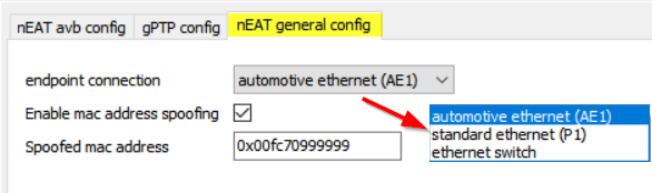
Endpoint Connection: Choose which Ethernet port is used to send and receive AVB Streams.
AE1: 100BASE-T1 Automotive Ethernet
P1: Standard Ethernet (100/1000BASE-T)
Ethernet Switch: The endpoint is connected directly to a port of the internal 88Q5050 Switch.
MAC Spoofing: The factory assigned MAC address may be overridden when this feature is enabled.
5.8.6. Media File Management
Media File Transfer
This inteface allows the user to upload media files to the endpoint, as well as download them to the computer or delete them.
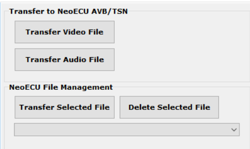
Maximum Media File Size
The maximum files size supported is 2 GB
Video Formats Supported
IEC61883-4 (Audio/Video)
Format: |
H.264 |
Resolution: |
|
level: |
Up to 4.1 |
Profile: |
|
Audio: |
|
CVF (Compressed Video Format):
Same as IEC61883-4, but no audio support.
Audio Formats Supported
IEC61883-6 (Audio)
Encoding: |
PCM (RAW) / S24_BE (Signed 24-bit Big Endian) |
Sampling Freq: |
48 KHz |
Channels |
1-32 |
AVDECC Audio Format (AAF)
Encoding: |
PCM (RAW) / S24_BE (Signed 24-bit Big Endian) |
Sampling Freq: |
48 KHz |
Channels |
1-32 |
Samples/Frame: |
6/12/48/64 |
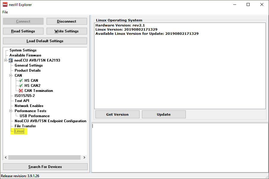
5.8.7. Linux
Here the versions of the hardware and Embedded Linux firmware can be seen.
The Linux firmware of can also be updated here for hardware versions rev3 and later. If you have hardware earlier than rev3, please contact customer support if you think a firmware update is needed.