3. A Tour of Gigastar Hardware
Before learning how to configure and set up the device, let’s examine the device from all sides to understand all of its interfaces and status indicators.
3.1. Label and Status Indicators
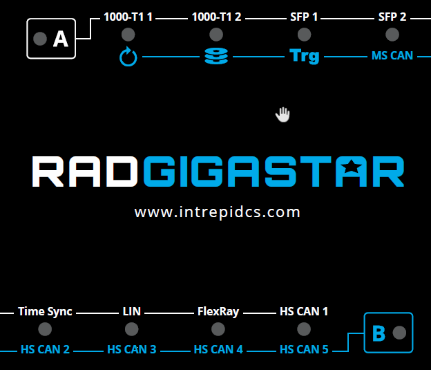
3.1.1. LED Indicators
The color of the LED within the active membrane button (A or B) confirms if the device is powered and if it has an active connection to Vehicle Spy on a host computer.
Indicator |
LED Behavior |
Status |
A/B Membrane Buttons |
White / Slow Flash |
Device Powered |
Green / Rapid Flash |
Online with Vehicle Spy (Ethernet) |
|
Blue / Rapid Flash |
Online with Vehicle Spy (USB) |
With the exception of the LEDs within the membrane buttons “A” and “B”, each LED has a dual use for status indication. The active membrane button determines which status any given LED is indicating.
3.2. Connector Interfaces
3.2.1. Device Power and Vehicle Network Interfaces
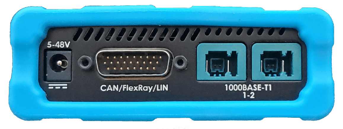
Barrel Jack: 5-48V (Left):
The device can be powered with this barrel jack using the DC supply provided with your purchase. If an alternate DC supply is used, it must be within the range of 5V-48V with a current capacity of 1 Amp, or the device may malfunction or be permanently damaged.
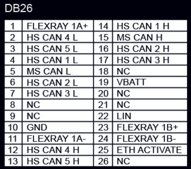
DB-26 Connector: CAN/FlexRay/LIN
In addition containing an alternate power connection, the CAN, LIN, FlexRay, and DoIP interfaces are located in this connector. The pin assignments are listed below and can also be seen on the bottom label of the device.
RAD-Gigastar Lite
Note that the RAD-Gigastar Lite does not contain the optional content of CAN, LIN, FlexRay and DoIP, therefore those pins are not used. However, the power and ground pins are identical to the fully featured RAD-Gigastar.
MATEnet Connectors: 1000BASE-T1 1-2 (Right)
Note connection system and pin assignments below.

Component |
TE Part Number |
|---|---|
Connector |
9-2302454-9 |
Insert Pin 4 |
2302450-1 |
Strain relief |
9-2302452-1 |
Crimp sockets |
1-1703930-1 |
Ports |
1000BASE-T1_P |
1000BASE-T1_N |
|---|---|---|
1000BASE-T1 (1-2) |
Pin 1 |
Pin 2 |
3.2.2. SFP and USB Ports
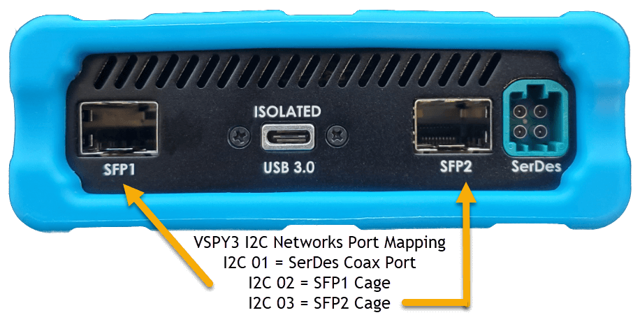
Note
The SerDes connector is not used at this time
SFP Ports
The RAD-Gigastar ships with two 1000BASE-T SFP modules which can be used in the sockets SFP1 and SFP2. Optical SFP modules are also available for purchase.
SFP Compatibility
While there are many types and many suppliers of SFP modules, it is important to use hardware that has been fully verified by ICS to insure full compatibility and reliable performance.
ICS Approved SFP Modules
Media |
Manufacturer |
Part Number |
10/100/1000BASE-T (Copper) |
Finisar |
FCLF8522P2BTL |
1000BASE-SX (Optical) |
Finisar |
FTLF8519P3BTL |
FS |
SFP1G-SX-85 |
Isolated USB 3.0 (Type C Connector)
This USB port is electrically isolated to protect it and a host computer from potential damage. It functions identically to connecting the RAD-Gigastar to a computer using one of the SFP ports. It has the advantage of supporting transfer speeds higher than 1Gbps, as well as allows the use of the SFP ports in a second active tap configuration.