2. Introduction and Overview
2.1. Introduction
Thank you for purchasing a RAD-Jupiter from Intrepid Control Systems (ICS). The RAD-Jupiter is 7-Port Automotive Ethernet Managed Switch Supporting 100BASE-T1, 100/1000BASE-T1, and 1000BASE-T. It also contains an integrated interface for CAN FD and LIN networks which can be used to monitor and transmit messages, and to create hardware simulations for network analysis.
Here are some of the noteworthy features of the RAD-Jupiter:
2.1.1. Product Features
Marvell 88Q5050 Switch
Embedded AVB/TSN Stack
2x GigE with Selectable PHYs
Marvell 88Q2112 PHY (100/1000BASE-T1)
USB 3.0 / Ethernet Bridge (Isolated for PC protection)
Fully-programmable scripting using CoreMini and Vehicle Spy Professional or Enterprise versions.
Intrepid Security Module supporting cybersecurity applications
8x dual purpose LEDs for network status and device configuration
Flexible power options (DB9/USB-C/barrel-jack)
Rugged aluminum case with shock-absorbing boots
Compact design: Dimensions: 7.30″ x 4.4″ x 1.6″
Light weight: less than 1 lb. (.45 kg).
2.1.2. Network Interfaces
7 Port Managed Switch
5x 100BASE-T1 Ports (NanoMQS connectors)
1x 1000BASE-T or 100/1000BASE-T1 (MATEnet connector)
1x 1000BASE-T or USB/GigE Bridge
2x CAN FD with programmable termination
1x LIN Channels
2.2. Operational Overview
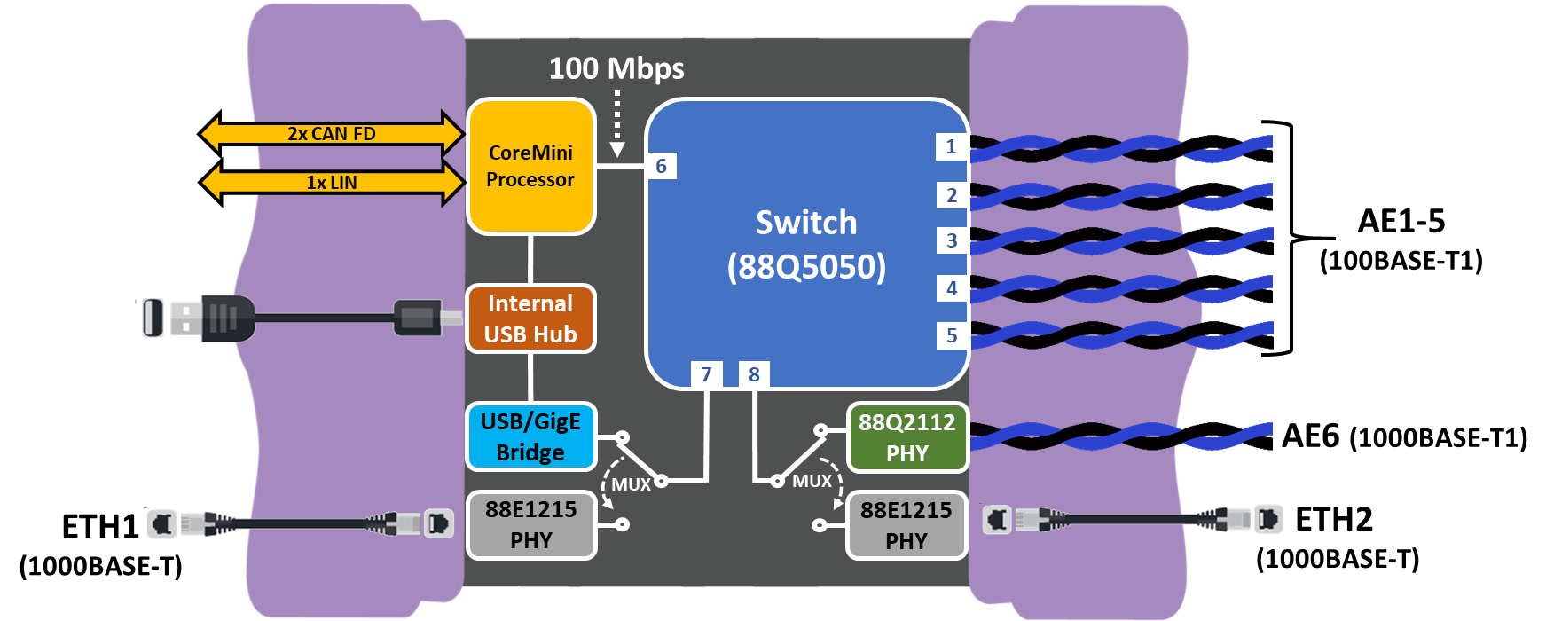
The RAD-Jupiter is a 8-port Ethernet Switch designed to automotive standards and to interface with automotive networks. The base functionality is a Layer 2 Switch. It also contains an embedded processor with CAN and LIN network interfacing, data acquisition, and simulation and scripting.

Switch Port |
Connector |
Link Speed |
|---|---|---|
Port 1 |
AE2 |
100BASE-T1 |
Port 2 |
AE1 |
100BASE-T1 |
Port 3 |
AE4 |
100BASE-T1 |
Port 4 |
AE3 |
100BASE-T1 |
Port 5 |
AE5 |
100BASE-T1 |
Port 6 |
NA |
100 Mbps to coremini processor |
Port 7 |
ETH1 |
1000BASE-T or USB Bridge |
Port 8 |
ETH2 |
1000BASE-T or 100/1000BASE-T1 |
Note port/connector assignments above
Switch Ports 1-4 are not connected to AE1-AE4 respectively (port 1 is not connected to AE1, etc.).
USB Bridge Operation
When port 7 is connected to the USB bridge, the RAD-Jupiter will appear as a Network Interface Card (NIC) to a connected computer (with properly installed driver). Ethernet traffic will pass directly between the switch and the computer. This configuration is intended for use with or without Vehicle Spy software.
2.2.1. Vehicle Network Interfacing
The primary function of this device is a layer 2 switch, but it can be used as an Ethernet interface with the CoreMini processor connected to Port 6 of the switch. This allows the PC to monitor live network activity as well as transmit Ethernet frames. The received network traffic arrives to the PC with a precision time stamp for data acquisition. Transmit and receive fuctions can be accessed using Vehicle Spy software our the Open Source API. For more information on how to use Vehicle Spy with this feature, reference Core Features
Monitoring and Simulating Ethernet Traffic
Note that not unlike ICS Ethernet tap devices, when used with VSPY or your own software, not all ports are directly accessible. The host computer is connected directly to a port of the 88Q5050 switch. To monitor or simulate Ethernet traffic, the switch needs to be configured to forward between the desired physical ports for your application.
2.2.2. Data Acquisition
With the use of Vehicle Spy or Intrepid APIs Acquisition of data from networks with precise control over collection parameters. The data can be captured in Vehicle Spy or using the Intrepid APIs.
2.2.3. Simulation and Scripting
Using Vehicle Spy you can define transmit messages with custom data and send them manually or on a schedule of your choosing. You can also write intelligent scripts that implement arbitrary logic and compile them into embedded scripts which can run within the device itself. This functionality allows you to create specialized test scenarios, and to simulate ECUs and gateways.
2.2.4. PHY Register access
In any mode, each PHY can be accessed by the embedded processor over MDIO in order to read and write configurations registers. More information can be found in PHY Dashboard
2.3. Package Contents
Your RAD-Jupiter package includes both hardware and software. Upon receipt, please remove, unwrap and inspect all its contents. If anything is missing or damaged, please contact Intrepid for prompt assistance, using the information at the end of this guide.
2.3.1. Hardware
Your RAD-Jupiter package includes the following:
The RAD-Jupiter device.
A standard 8-wire Ethernet cable (CAT5e)
A 100/1000BASE-T1 cable (MATEnet Connectors)
Nano-MQS Connector and Terminal kit
A standard USB Type B to Type C SuperSpeed cable
A 12 Volt Power Supply
2.3.2. Software
Unless physical media was specifically requested, your box should contain a reference card with instructions on where to download the device drivers and any other purchased software. If your media or reference card cannot be located, please contact Customer Support.
2.4. Hardware Requirements
2.4.1. Device Power
The RAD-Jupiter can be powered in 3 different ways
DC supply: This device comes with a DC supply rated for this device. If an alternate supply is used, insure that the voltage is between 5V-40V and is rated for at least 1 Amp.
Certified USB 3.0 Port: Earlier versions or uncertified devices may not supply the current required for reliable operation. If you are unsure of your USB port’s power capabilities, use one of the other 2 options to provide power to the device.
9-pin DSUB (See section 2.2 for pin assignments)
2.4.2. Computer Interface
Connection to a computer is needed both for configuration of the tool as well as to communicate with the device if you intend to use Vehicle Spy or Intrepid’s available API.
As a hardware device, there are no specific requirements on the computer aside from the proper USB interface and the proper device driver installed. Instructions on installing the device driver are covered later with the installation of software.