 Part 3 - Setup the Graphical Panel
Part 3 - Setup the Graphical Panel
Part 3 - Setup the Graphical Panel
Graphical Panels are similar to the graphical user interface (GUI) of an application. Once built, they allow a user having no knowledge of Vehicle Spy to perform complex tasks with Vehicle Spy. In this tutorial, a very basic Graphical Panel with only a few tools will be constructed. It is possible to have dozens of controls across multiple panels.
Select Measurement > Graphical Panels from the main menu.
To add a control, click on the control from the palette, and click on the graphical panel where it needs to be. Start by clicking on the LED control
(Figure 1: ), then click anywhere in the graphical panel to place the LED. The LED should now appear in the graphical panel
(Figure 1:
), then click anywhere in the graphical panel to place the LED. The LED should now appear in the graphical panel
(Figure 1: ). The LED can be resized by dragging the blue boxes surrounding it to the desired dimensions.
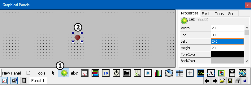
Click on the LED in the graphical panel. The Properties pane contains options for configuring the control. If the Properties pane is not visible, be sure that the LED and
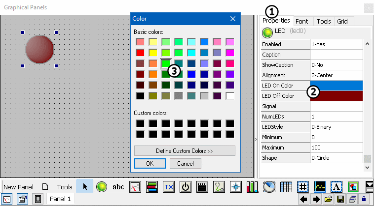
Properties Tab are selected (Figure 2:). From the Properties pane click once on the LED On Color property
(Figure 2:) then double click to open a color picker where the On color of the LED can be selected. Make this LED green
(Figure 2: ). Do the same for the LED Off color, but choose a darker red as the color.
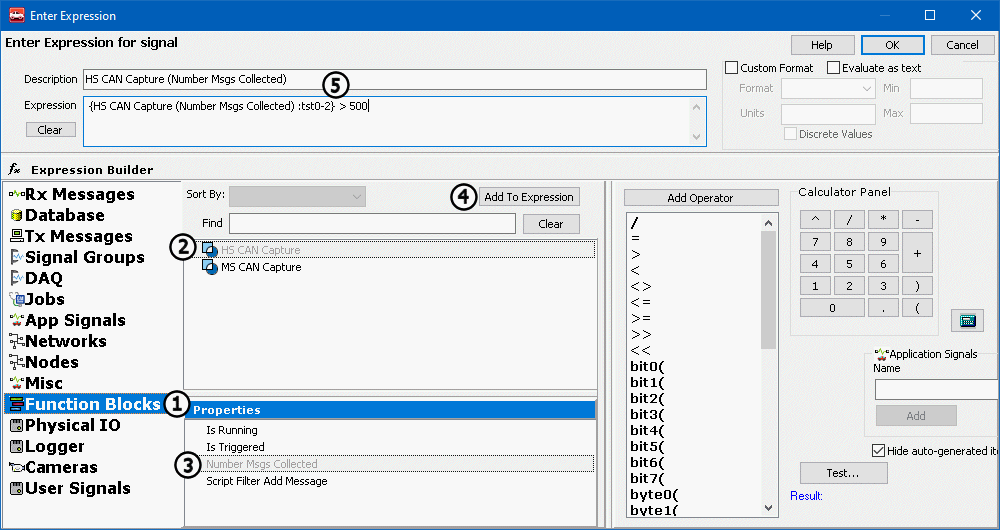
Double click the Signal property to open the Expression Builder. This property is what links the control to a Vehicle Spy data item.From the Expression
Builder window, select Function Blocks (Figure 3:).A listing of Function Blocks that were previously
created are now displayed in the center of the window (Figure 3:), select HS CAN Capturefrom this list.
The Properties pane at the bottom will update with the available properties for the selected data item, select Number Msgs Collected
(Figure 3:). Adding the selected item to the expression field can be done a few ways. Double click the item to add, or
once it is selected press the Add To Expression button (Figure 3: ). Once the property is added to the
Expression field (Figure 3:
). Once the property is added to the
Expression field (Figure 3: ) enter > 500
(approximately the number of HS CAN messages in the simulation file) without quotes to the end of the text surrounded by braces {}. When the number of messages collected
is greater than 500 the LED will be lit.
) enter > 500
(approximately the number of HS CAN messages in the simulation file) without quotes to the end of the text surrounded by braces {}. When the number of messages collected
is greater than 500 the LED will be lit.
Create and configure a second LED using the method above. This time use the Number Msgs Collected property of MS CAN Capture and instead of > 500 messages use >370 messages.
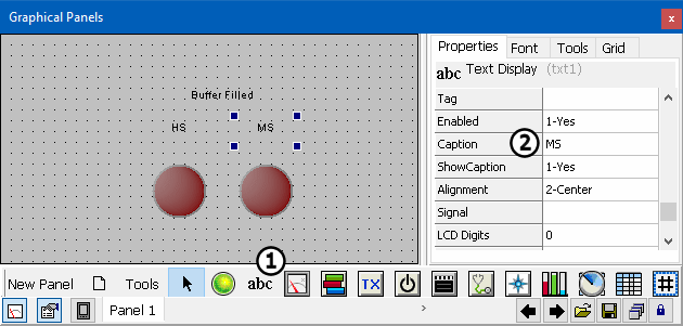
Text display controls can be used to display text values, they can also be used as labels.This tutorial will use them to label the LEDs. Click on the Text tool
(Figure 4:) and click anywhere in the graphical panel to place the tool. To choose text for the label, change the
Caption property (Figure 4:)to the needed text.Change this caption to Buffer Filled. Place this
text above the LEDs. Create two more labels, one HS and another MS for each LED.
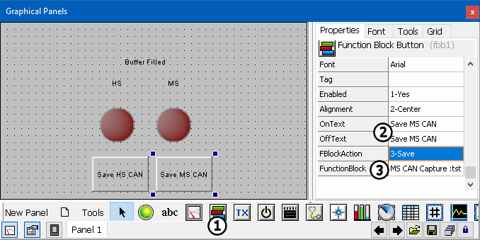
Click the Function Block button (Figure 5:) and place it on the graphical panel. Once the button is placed,
change the OnText and the OffText property to Save HS CAN (Figure 5:).
Next, double click the FBlockAction property just below OffText and select 3-Save. Double click the FunctionBlock property
(Figure 5:) and select HS CAN Capture from the pull down. Create a second
Function Block button. This time change the On and Off text to Save MS CAN and choose MS CAN Capture for the Function Block.
Don't forget to change Function Block Action to 3-Save. The Function Block buttons will save the Capture Function Blocks' buffers.
 Spy Documentation - (C) Copyright 1997-2022 Intrepid Control Systems, Inc.

