 Message Signal Type DTC
 Message Signal Type DTC
The DTC (Diagnostic Trouble Code) format is an automotive industry standard. The format relies on two bytes to form an alpha numeric code.*
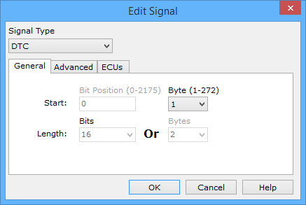
By setting up the Signal Type pulldown to DTC in the Edit Signal dialog (Figure 1), a DTC signal will be setup. Just select the Start byte where the DTC is located in the message and that's it!
Some limits are placed on the dialog to help avoid mistakes. DTC signals are byte aligned, so the Bit Position field is disabled. DTC signals are 2 bytes long, so the Length is already set to this value for you. To define the DTC further with a text description you can use a DTC Database.

Byte #: | Byte 1 | Byte 2 |
Bit #: 0 1 | 2 3 | 4 5 6 7 | 8 9 10 11 | 12 13 14 15
Bits 0 & 1 - defines the only letter in the DTC.
00 = P = Powertrain
01 = C = Chassis
10 = B = Body
11 = U = serial data
Bits 2 & 3 - defines first digit of DTC.
00 = 0
01 = 1
10 = 2
11 = 3
Bits 4-7, 8-11, 12-15 - defines last 3 digits of DTC.
Uses Binary Coded Decimal (each group of 4 bits (nibble) = 0-9).
Table 1 illustrates an example of the translation between data bytes $92 $34 and DTC B1234.
| Format | Message Byte 1 | Message Byte 2 | Description | |||
|---|---|---|---|---|---|---|
| Hexadecimal | 9 | 2 | 3 | 4 | Data bytes $92 $34 | |
| Binary | 10 | 01 | 0010 | 0011 | 0100 | Bits 0 to 15 |
| DTC | B | 1 | 2 | 3 | 4 | DTC B1234 |