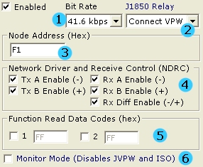
Figure 1 - The LBCC Node Address, NDRC, and Function Read Data Codes Setup
J1850 PWM (Ford SCP) - neoVI
Main
Applies to
neoVI Blue
To implement J1850 PWM communications neoVI uses the Ford SCP LBCC communications IC with the Ford specified physical layer. It optionally lets you monitor the entire network using special monitor mode firmware. The LBCC IC allows you to setup a number of parameters that control its operation. When enabled, the neoVI Firmware supplies monitor mode and the LBCC provides transmit operations.
First, you can set the bit rate of the SCP network (figure 1 : bubble 1). The standard network bit rate is 41.6 kbps. The higher speed 83.3 kbps is sometimes used on the network for special network operations. Special Monitor mode only supports the 41.6 kbps rate.
The OBD connector used in neoVI connects the J1850 VPW network to the J1850 + line. neoVI contains a relay the can switch the JPWM + signal on to that line instead of JVPW. This allows you to use one connector with both protocols. You can have neoVI default to either connecting VPW (default) or PWM (Figure 1: bubble 2). You can control the relay at run time using a neoVI virtual network can message.
You can set the Node Address of the Ford SCP node. This is shown in the figure 1: bubble 3. This is used for setting the source id and is used when the LBCC generates In frame responses (IFRs). This address must be unique for each node on the SCP network.
Next, you can set the Network Driver and Receive Control Register (NDRC) of the LBCC. This is shown in figure 1 bubble 4. The NDRC is a register in the LBCC which allows you to transmit or receive on portions of the dual wire network. Normally, these should all be checked.
The LBCC allows you to optionally handle two function read data message parameters. These are setup in figure 1 : bubble 5. If you want to handle a function read data message, check the number 1 or 2 and enter the function code. These settings are entered in Lookup Table 2 of the LBCC device. You can set the actual data for the function code with the "LBCC Set FRead data" neoVI virtual network command.
You can setup the LBCC look up table 1 (figure 2). Lookup table 1 controls what functional messages the LBCC should receive. You can have up to 31 entries in this table. In figure 2, we setup the LBCC to receive three functional messages including 0x1E, 0xF1, and 0x22. Blank spaces in the table are ignored.
Special Monitor mode allows you to monitor all traffic on the SCP network. To enable this node click the check box in figure 1 bubble 6. This enables special firmware in neoVI that monitors and decodes the raw SCP waveform. When this is done, both J1850 VPW and ISO/KW2k protocols are disabled. You can still use the Ford LBCC channel. All monitor mode messages come across on the J1850VPW network.
Node Address - The SCP Node address is used for three purposes. First, the node address is the third byte of every transmitted message (the source address). Next, the address is used for node address acknowledgement. Finally, it is used to determine which physically addressed SCP messages should be received.
Tx Driver Enable -These two bits enable network drivers A (bus -) and b (bus +). When set, each bit will enable the corresponding output pin driver. When the bit is clear the pin is tristated.
Rx Enable Bits - These three bits control the inputs into the LBCC bit decoder. The receivers are enabled when the bits are a "1". Disabled receivers force a "stuck active" condition to the bit decoders.
Figure 1 - The LBCC Node Address, NDRC, and
Function Read Data Codes Setup
Figure 2 - LBCC Lookup Table 1 setup.
| neoVI Documentation - (C) Copyright 2000-2020 Intrepid Control Systems, Inc. |
Last Update: Thursday, July 09, 2009