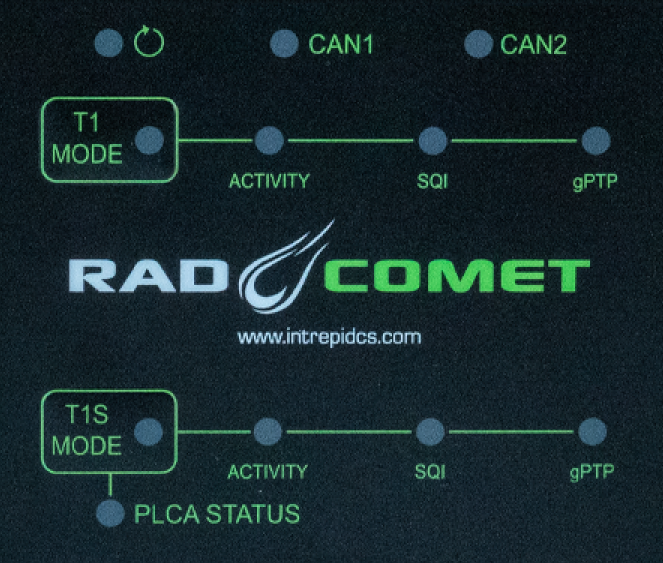
The mode each PHY is displayed by the status LED within the corresponding
membrane button.
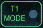
PHY Mode
Link Speed
AE1
Cyan = Auto (Link Down)
Slow Flash: Link Down
Fast Flash: 100 Mbps
Green = Master
Blue = Slave
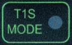
AE2
CSMA/CD Mode
Cyan
Always 10Mbps
PLCA Coordinator
Green
PLCA Follower Node
Blue
Changing between coordinator and follower node
The RAD-Comet can be toggled between coordinator and follower by holding “T1S MODE” for 3 seconds.
The node ID of the follower is configured using neoVI Explorer.
SQI is a 3-bit value reported by the PHY that correlates
with the BER (Bit Error Ratio) of the link communication. The behavior of the
SQI LED is shown below.
The PLCA status is reported by the 10BASE-T1S PHY and
displayed below the T1S Mode button according to the following table.
Green
Beacon Present
Red
Collision
Yellow
Jabber Detected
Magenta
Unexpected Beacon
Blue
Empty Cycle
Cyan
RX in Transmit Opp
Note:
The settings described in this section can also be modified using neoVI Explorer or Intrepid’s
open source cross-platform device communication API. (explained later in this guide)
You may see all the LEDs on the top label flashing synchronously.
This means the device is in bootloader mode, which should only happen when flashing the device’s firmware.
If this is observed unexpectedly or following a firmware update, please contact customer support for assistance.
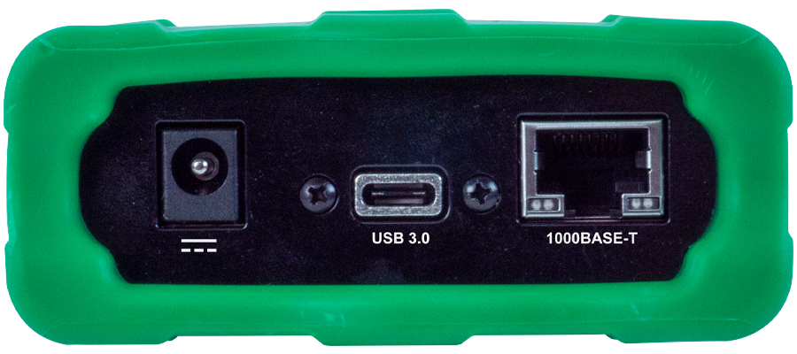
The device can be powered using a DC supply between 5.5-40V volts with a minimum power of 10 Watts.
Using a power supply that does not meet these requirements may cause the device to
malfunction or be permanently damaged.
This serves as a connection to a host computer for configuration, firmware updates, and PHY register access.
The RAD-Comet can also be powered through this connection, provided the host port meets USB 3
power.
The industry standard RJ-45 Ethernet jack is a 10/100/1000BASE-T port that can be used to
connect to a host computer or be used as a network port for sending and
receiving Ethernet traffic.
Link LED (Green): Indicates that a valid link has been established between your device and another 10/100/1000 Ethernet device.
Activity LED (Orange): Flashes when traffic passes in either direction over the attached Ethernet cable.
In normal operation you should see the Link LED always on, and the Activity LED flashing at a variable rate, with faster flashing meaning that more data is being transferred.
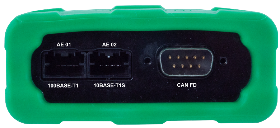
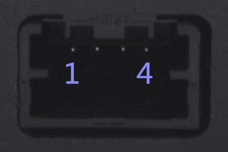
The mini-50 connector on the left is a 100BASE-T1 port with the following
pin assignments. Looking into the connector, the leftmost pin is Pin #1
with pin indexing increasing from left to right.
The mini-50 connector on the right is a 10BASE-T1S port with the following
pin assignments. Looking into the connector, the leftmost pin is Pin #1
with pin indexing increasing from left to right.
The DB-9 connector on the right holds two CAN FD channels and can also be used to power the RAD-Comet.
Pin assignments are listed in the table below. See this section for
detail on power supply requirements.