Make sure this is the correct user guide for your hardware
The RAD-Comet comes in 3 variants, each with its own user guide. A comparison of the variants as well as links to the other user guide can be found here
2. Introduction and Overview
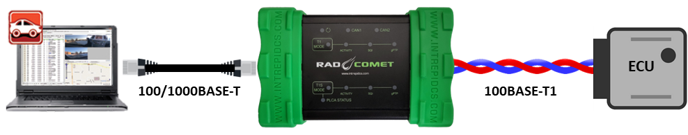
Thank you for purchasing Intrepid Control Systems’ RAD-Comet. You will find it a valuable tool for 10BASE-T1S In-Vehicle Network development, as well as working with 100BASE-T1 and CAN FD.
2.1. RAD-Comet Variants
Note that there are 3 variants in the RAD-Comet family. Below is a table summarizing the primary differences as well as links to the user guides of the variants.
Network Interface |
RAD-Comet** |
||
|---|---|---|---|
10BASE-T1S |
1x LAN8671 |
2x LAN8671 |
6x AD330X |
100BASE-T1 (88Q1010) |
1x 88Q1010 |
0 |
0 |
100/1000BASE-T1 |
0 |
1x 88Q2220M |
1x 88Q2220M |
10/100/1000BASE-T |
1 |
1 |
1 |
CAN-FD |
2 |
2 |
2 |
LIN |
0 |
1 |
1 |
** You are currently viewing the user guide for this device.
2.2. Package Contents
Upon receipt, please remove, unwrap and inspect all its contents. If anything is missing or damaged, please contact Customer Support for prompt assistance.
2.2.1. Hardware
Your package includes the following:
The RAD-Comet device.
1x standard 8-wire Ethernet cable (CAT6)
A reference card with a hyperlink to Drivers and Software
1x standard USB Type A to Type C SuperSpeed cable
If purchased, the following accessories may also be present.
A 12 Volt Power Supply
2.2.2. Software
Unless physical media was specifically requested, your box should contain a reference card with instructions on where to download the device drivers and any other purchased software. If your media or reference card cannot be located, please contact Customer Support.
2.3. Device Overview
The RAD-Comet contains a number of different network interfaces and features to allow it to support a wide variety of use cases for In-Vehicle Networking development and testing.
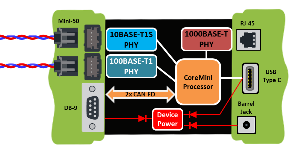
2.3.1. Network Interfaces
Physical Layer |
Quantity |
10BASE-T1S (LAN8671) |
1 |
100BASE-T1 (88Q1010) |
1 |
10/100/1000BASE-T |
1 |
CAN-FD |
2 |
2.3.2. RAD-Comet Block Diagram
2.3.3. Product Features
Automotive Voltage Range Operation (5.5V-40V)
Temperature Range: -40°C to +85°C
Low Power Consumption
Automatic or static master/slave PHY configuration (T/T1 networks)
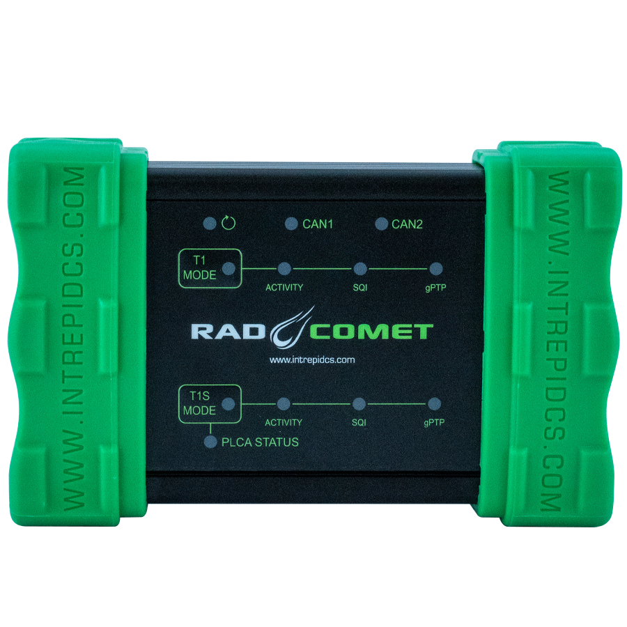
LED indicators for Link Status and Network Activity
Standalone mode including scripting, receive messages, transmit messages, expressions, and Gateways
10 ns message time stamping precision
Field-upgradeable flash firmware
Compact design: 5.35” x 3.46” x 1.46” (13.6 x 8.8 x 3.7cm)
Rugged aluminum enclosure with rubber bumpers for durability
Light weight: less than 1 lb. (.45 kg)
1 Year Limited Warranty
2.4. Operational Overview and Use Cases
The following section will outline some of the more common use cases, however it should not be interpreted as a complete list of the device’s full capabilities.
2.4.1. Media Conversion
The RAD-Comet can be used as a media converter between 10BASE-T1S and any of the other Ethernet physical layers available on the device.
10BASE-T1S ⇔ 10/100/1000BASE-T
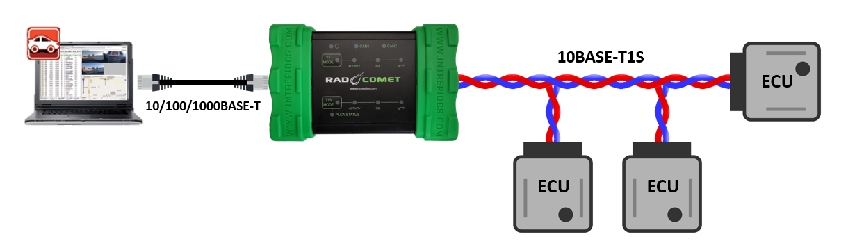
10BASE-T1S ⇔ xBASE-T1
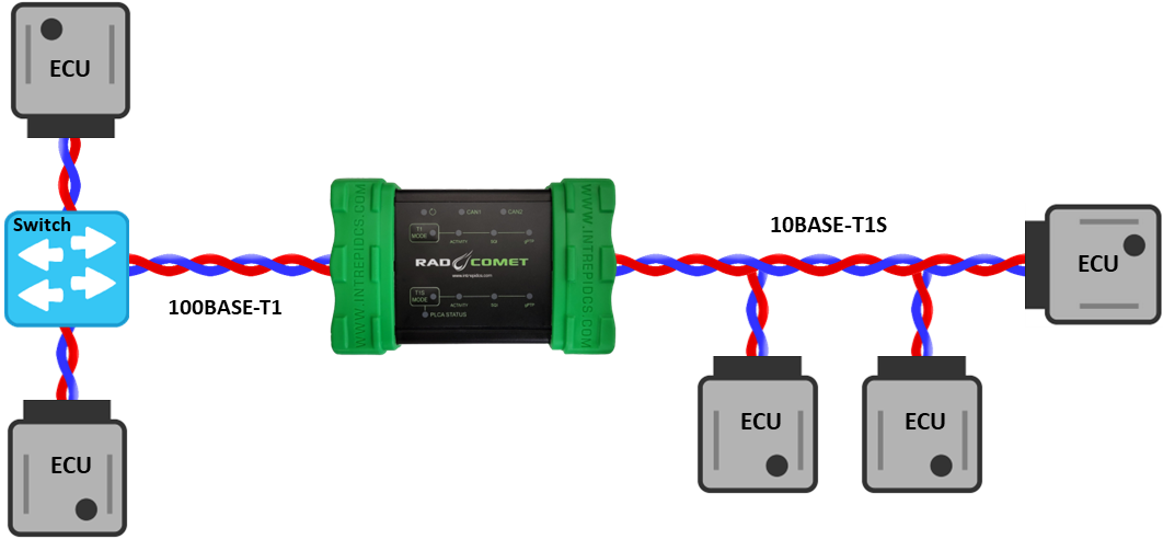
10/100/1000BASE-T ⇔ xBASE-T1 Media Conversion
2.4.2. Stand-Alone Gateway
Elaborate gateways can be implemented between any of the networks available on the RAD-Comet.
CAN/Ethernet Gateway
Payloads can be extracted from frames arriving on one network, placed into a different PDU structure with a different header and sent to another network.

Examples of this utility include (but not limited to):
Networking devices from different architectures for a proof-of-concept
Networking devices during the transition from one vehicle architecture to the next
Streaming select (or all) network traffic for logging and analysis
Ethernet/Ethernet Gateway
Frames can arrive on one Ethernet network and sent out to another network directly, or after changing anything in the header or payload.
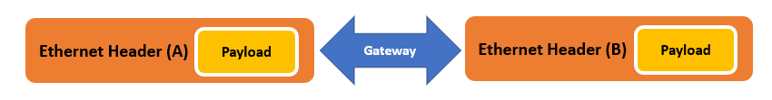
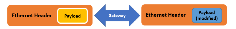
This functionality can be used to realize many novel functions useful in vehicle testing.
For Example:
Changing frame destination
MAC Spoofing
Layer 3/4 Address Translation
Payload scaling
Payload manipulation (Boundary testing, fault injection, penetration testing, etc.)
2.4.3. Simulation and Scripting
Using Vehicle Spy you can define transmit messages on any network with custom data and send them manually or on a schedule of your choosing. You can also write intelligent scripts that implement arbitrary logic and compile them into embedded scripts which can run within the device itself. This functionality allows you to create specialized test scenarios, and to simulate ECUs and gateways.
2.4.4. PHY Register access
In any mode, each PHY can be accessed by the embedded processor over MDIO in order to read and write configurations registers. More information can be found in PHY Dashboard
2.5. Hardware Requirements
2.5.1. Device Power
The RAD-Comet can be powered in multiple ways.
DC supply:
The RAD-Comet requires DC voltage source within the range of 5.5V-40V and a power rating of at least 10 watts. The device can be powered using the barrel jack or DB-9 connector.
See DB-9 Connector for specific pin assignments.
Certified USB 3.0 Port:
Powering the RAD-Comet with a USB port that is not certified to USB 3.0 may not supply the current required for reliable operation. If you are unsure of your USB port’s power capabilities, use one of the other 2 options to provide power to the device.
Using older USB Ports
If using an underpowered USB port or hub, always connect the DC Supply prior to connecting the device to this hub or port. Failing to do this will not damage the device, but it has been observed that the device may not boot and function properly.
2.5.2. Computer Interface
Connection to a computer is needed both for configuration of the tool as well as to communicate with the device if you intend to use Vehicle Spy 3 software , Intrepid’s Open Source API or Intrepid’s neoVI API
As a hardware device, there are no specific requirements on the computer aside from the proper interface and the proper device driver installed. There are 2 ways to connect the RAD-Comet to a host computer.
1000BASE-T
No specific drivers are required to connect the RAD-Comet to a host computer using a standard 100/1000BASE-T Ethernet Adapter.
IT Policies
With IT security a growing concern, many IT departments block certain types of Ethernet traffic and communication. In some cases, this has been found to interfere with Intrepid devices connected to a host computer using Ethernet. If you find you are having trouble please contact our Customer Support.
USB 3.0 (Type C Connector)
This port can be used to connect RAD-Comet to a host PC using a driver that is installed as part of the Vehicle Spy installation or by installing Intrepid’s API Kit.