3. Description of RAD-Moon Interfaces and Indicators
Let’s now take a short tour of the RAD-Moon, looking at the device’s external components and explaining what each does. The RAD-Moon is designed so that all of its components are located on its two sides, to make the device easier to use in cramped quarters. We’ll identify the sides by the type of Ethernet port each contains, calling one the Conventional Ethernet Side and the other the Automotive Ethernet Side.
3.1. Conventional Ethernet Side
Figure 2 shows the side of the RAD-Moon that attaches to a conventional Ethernet network. The two components are as follows:
- RJ-45 Port: An industry-standard conventional Ethernet jack.
- Mini-USB Port: A standard mini-USB port.
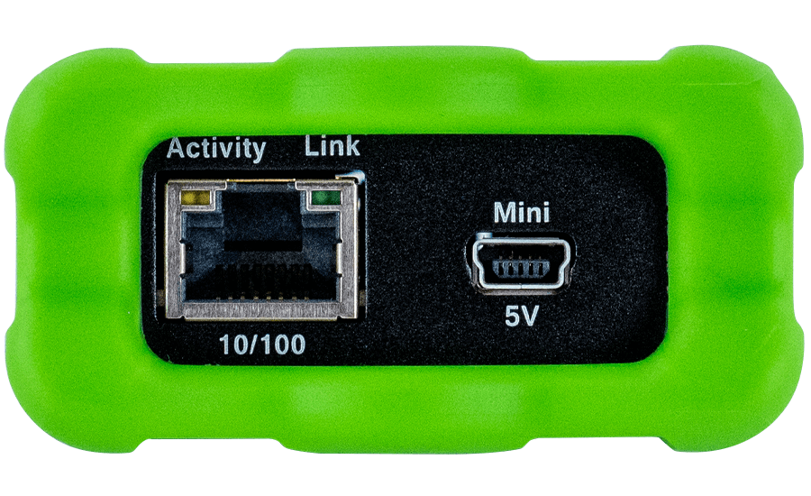
Figure 2: RAD-Moon Conventional Ethernet Side. Left, the standard Ethernet RJ-45 jack with integrated Link and Activity LEDs; right, a mini-USB jack that provides power to the device.
The RJ-45 port has a pair of integrated LEDs that provide information about the RAD-Moon’s conventional Ethernet connection:
- Link LED (Green): Indicates that a valid link has been established between the RAD-Moon and another 10/100 Ethernet device.
- Activity LED (Orange): Flashes when traffic passes in either direction over the attached Ethernet cable.
In normal operation you should see the Link LED always on, and the Activity LED flashing at a variable rate, with faster flashing meaning that more data is being transferred.
The RAD-Moon’s standard 10/100 Ethernet connection will automatically negotiate to match the speed of the Ethernet device to which it is attached. In most cases it will run at 100 Mb/s, though it will support connection to a device that runs at 10 Mb/s. The RAD-Moon can be forced to run at either 10 Mb/s or 100 Mb/s by forcing the other device to the desired speed.
3.2. Automotive Ethernet Side
This side of the RAD-Moon (Figure 3.1 and Figure 3.2) contains just one interface: a Molex Mini50 jack. While there is no standardized Automotive Ethernet connector type, the Mini50 is used by many BroadR-Reach devices, including Broadcom switches and other Intrepid AE hardware. The BroadR-Reach connection automatically configures itself as master or slave as needed.
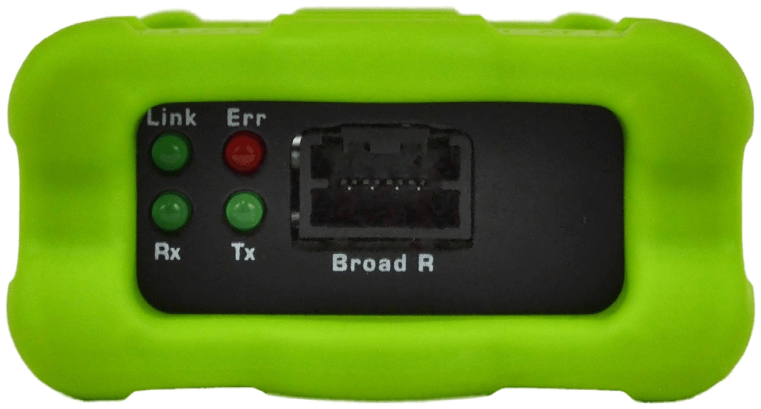
Figure 3.1: RAD-Moon BCM89810 Automotive Ethernet Side. The Mini50 BroadR-Reach connector can be seen here in the center, with the bank of status LEDs to the left.
If you have Broadcom BCM89810 BroadR-Reach PHY then you will see Four LEDs indicate the status of the RAD-Moon’s AE link:
- Link (Green): Turns on when the RAD-Moon is connected to an active Automotive Ethernet device, and remains on as long as the link is maintained.
- Err (Red): Flickers when an error is detected by the RAD-Moon’s BroadR-Reach PHY, such as a data transmission error being seen in a received frame.
- Rx (Green): Flashes when data is received by the RAD-Moon from the connected Automotive Ethernet device.
- Tx (Green): Flashes each time data is transmitted by the RAD-Moon to the attached Automotive Ethernet device.
Under normal circumstances you will see the Link LED always on, with the Rx and Tx LEDs flashing at different rates depending on how much data is being sent by each device connected to the RAD-Moon. Assuming that all devices are functioning correctly, the Err LED should rarely, if ever, light up.
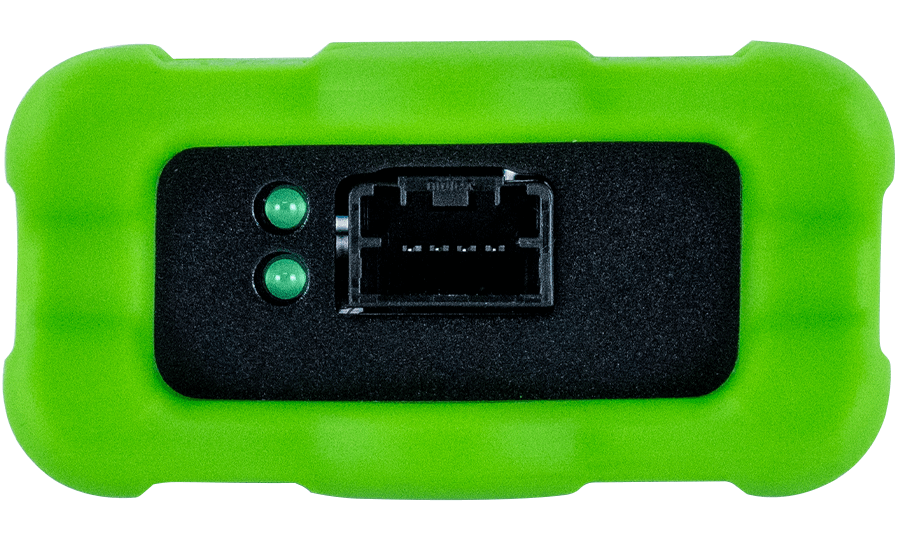
Figure 3.2: RAD-Moon TJA1100 Automotive Ethernet Side. The Mini50 BroadR-Reach connector can be seen here in the center, with the bank of status LEDs to the left.
If you have TJA1100 PHY, serial number greater than 023599 then you will see Two LEDs indicate the status of the RAD-Moon’s AE link:
- Link (Green): Turns on when the RAD-Moon is connected to an active Automotive Ethernet device, and remains on as long as the link is maintained.
- Rx (Green): On dimly when a significant amount of traffic is being received by the Rad-Moon from the connected Automotive Ethernet device (Minimum 5Mbps required to recognise.)
3.3. BroadR-Reach Connector Pinout
The pinout for the RAD-Star’s Mini50 jacks can be found in Table 1, with the pin numbers illustrated in Figure 4.
| Pin # | Label | Description |
| 1 | No Connect | |
| 2 | TRD+ | Data transmit and receive, positive |
| 3 | TRD- | Data transmit and receive, negative |
| 4 | No Connect |
Table 1: RAD-Moon BroadR-Reach Mini50 Jack Pinout.
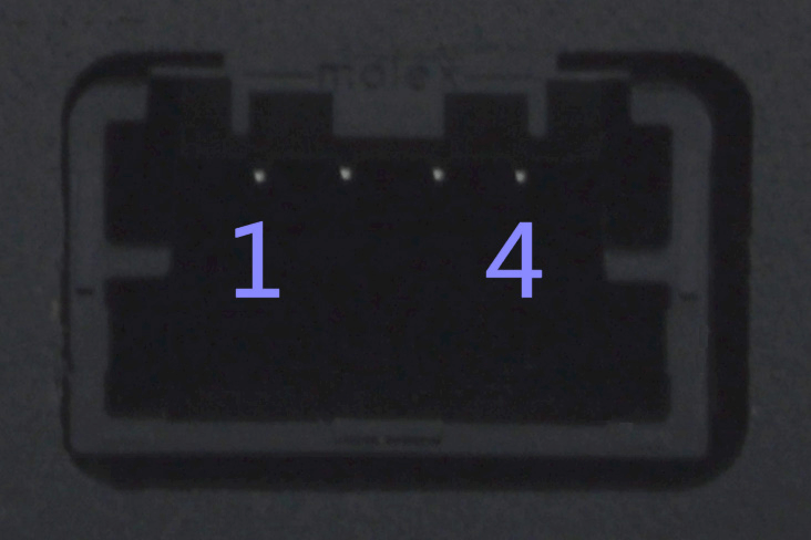
Figure 4: RAD-Moon BroadR-Reach Mini50 Jack with Pin Numbers. Pins are numbered 1 to 4 from left to right looking at the jack, as shown.
Pin and Connector Part Number
pin part number is WM25289CT-ND
Digikey link - https://www.digikey.com/en/products/detail/molex/5600230444/7042085
DataSheet - https://www.molex.com/pdm_docs/ps/PS-560023-001.pdf
connector is WM9381-ND
Digikey link - https://www.digikey.com/product-detail/en/molex/0347910040/WM9381-ND/3202544
DataSheet - https://www.molex.com/pdm_docs/ps/PS-34791-020.pdf
We also have cables on our website. If you need different ends, cutting the cable would give you 2 ends for your own connections. https://store.intrepidcs.com/BR-CABLE-1-MINI50-p/br-cable-1-mini50.htm