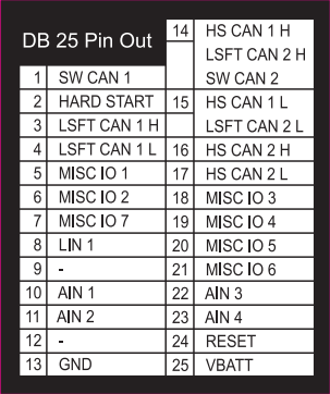
3. A Tour of neoECU-12 Hardware
3.1. Case and Overall Design
The neoECU-12 is enclosed in a lightweight plastic case. The device has been designed and tested for in- vehicle use, and is operational in a temperature range from -40°C to +85°C.
The pinout for the DB25 male connector is on the bottom of the case.

3.2. Front side of Case
The front side of the case contains the DB25 male connector.

3.3. Back side of Case
The back side of the case contains the serial number and tri-color LEDs.

3.4. Controlling the Tri-Color LEDs
The neoECU-12 has default behavior for the first two tri-color LEDs. The 1st LED is for HS CAN 1, the 2nd LED is for HS CAN 2 and the 4th LED is for LIN.
Interpretation of RGB LED Colors
These are “RGB” LEDs because they contain separate red, green and blue elements. For networks, each indicates a different aspect of the device’s overall status:
Green: Device is transmitting messages on this channel.
Blue: Device is receiving messages on this channel.
Red: Device is detecting errors on this channel.
It is possible for more than one LED component to be lit, producing the following results:
Green+Blue (Cyan): Device is transmitting and receiving on this channel.
Green+Red (Yellow): Device is transmitting and detecting errors on this channel.
Blue+Red (Magenta): Device is receiving and detecting errors on this channel.
Green+Blue+Red (White): Device is transmitting, receiving and detecting errors on this channel.
LED3 blinks magenta when a function block script is running.
In bootloader mode, all five LEDs blink red in succession.
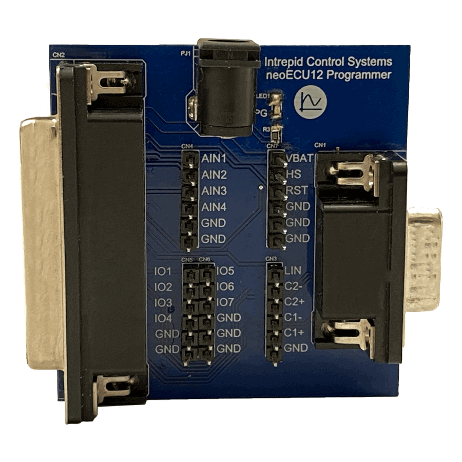
3.5. Optional neoECU 12 Programming Board
Programming Board for the neoECU-12. You can use with a ValueCAN 4 Series device to flash scripts into the neoECU-12.

Note
12 VDC power is required to power the NEOECU-12-PB. Use the NEOVI-PS Power Supply (not included) or your own 12 VDC power supply via the barrel connector on the board.