5. Device Configuration
The neoVI FIRE 2 comes with a USB host port that allows other devices to be plugged into it (see Figure 6 in Section 3.3). Due to the difficulties associated with driver development, this port is intended for specific devices rather than general purpose use. It is especially designed to work with devices such as the Intrepid neoVI MIC microphone/trigger pendant, or the RADMoon (as seen in Section 6.3)
5.1. Starting and Using neoVI Explorer
The neoVI Explorer utility allows you to connect to, manage and configure all of your Intrepid Control Systems hardware, including the neoVI FIRE 2. It is supplied both as an integrated feature of Vehicle Spy, and as a standalone program.
This section will describe general features and the basics of using neoVI Explorer, so you will understand the utility well when we get into settings specific to the FIRE 2.
Starting neoVI Explorer from within Vehicle Spy
There are several ways to open neoVI Explorer from within VSpy. These are probably the two easiest, since they are accessible at all times:
Menu Item: Click the Setup menu and then select Hardware.
Hardware Setup Button: Click the
 button located in the main Vehicle Spy toolbar
just under its menu (Figure 56).
button located in the main Vehicle Spy toolbar
just under its menu (Figure 56).
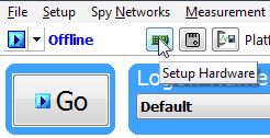
Figure 56: Starting neoVI Explorer from within Vehicle Spy.
Note that you cannot start neoVI Explorer when Vehicle Spy is online (even if in simulation mode). If you attempt to do so, VSpy will prompt you to either go offline and launch neoVI Explorer, or remain online and return to Vehicle Spy.
Starting neoVI Explorer as a Standalone Program (with Vehicle Spy Installed)
If you want to work with your neoVI FIRE 2 without opening Vehicle Spy, you can launch neoVI Explorer directly. Open the Start Menu, navigate to the IntrepidCS folder, then under the Vehicle Spy 3 subfolder, select neoVI Explorer (Figure 57).
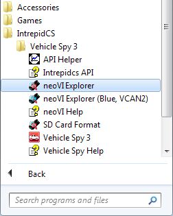
Figure 57: Starting neoVI Explorer Directly with Vehicle Spy 3 Installed.
Starting neoVI Explorer as a Standalone Program (API Kit Installed)
If you installed the API kit and support files instead of Vehicle Spy, you can run neoVI Explorer from the Start Menu using the same basic process as described above. The only difference is the name of the subfolder, so you will navigate to the IntrepidCS folder, then open the ICS API Install Kit subfolder, and finally select neoVI Explorer (Figure 58).
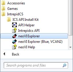
Figure 58: Starting neoVI Explorer as a Standalone Program from the API Kit.
Connecting to the FIRE 2
When neoVI Explorer loads, it will start up with the first hardware device it can find selected in the menu pane on the left. You should see your neoVI FIRE 2 listed here, along with its serial number, which begins with “CY”. If you don’t see the FIRE 2, but do see other Intrepid devices, be sure to scroll down to look for it. If it is still not visible, either its drivers have not been installed correctly or it is not powered properly; please refer to Chapter 9 for assistance.
To manage your FIRE 2, click on its entry in the navigation pane (if it is not already highlighted) and then press the Connect button. After successfully connecting to the device, you will see a “thumbs up” icon next to the device’s name, and checkmarks will appear next to currently-enabled networks in the explorer area on the left. You should also see a message in the message box on the right saying neoVI FIRE2 CYxxxx settings have been read. This tells you that neoVI Explorer has loaded the current settings from the FIRE 2. The information in the upper right-hand part of the window is device-specific and described in Section 5.2. The screen as a whole should appear similar to that shown in Figure 59 (but note that the version number shown at the bottom may be different).
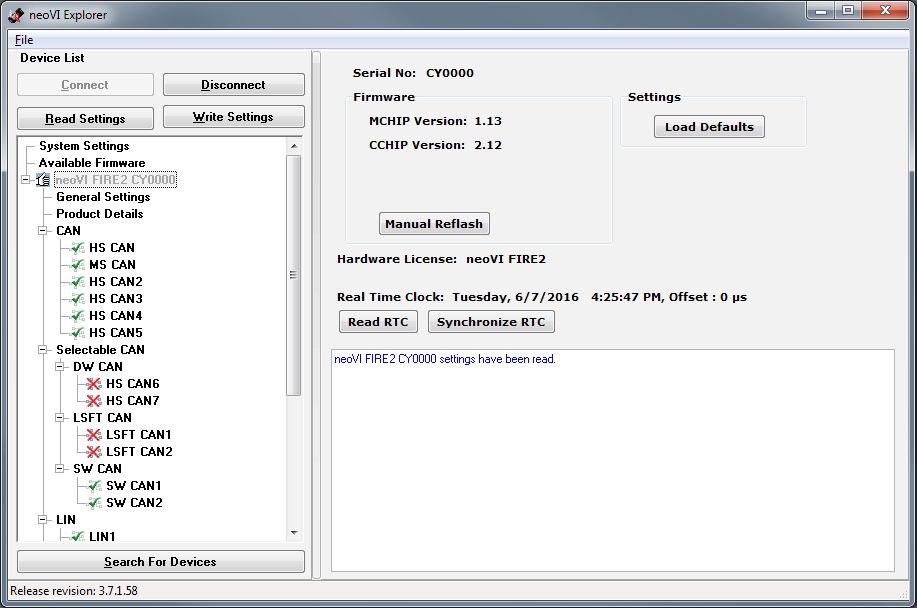
Figure 59: Typical neoVI Explorer Window After Initial Connection to the neoVI FIRE 2.
Note
It is possible to click on various parameter groups at any time, but they will not show valid data until you connect to the device. Remember also to connect to the device before making changes, or those alterations will be erased when you do connect and the settings in the hardware are loaded.
Writing and Reloading Settings
To avoid potential problems, neoVI Explorer will not save any changes to device parameters until you instruct it to do so. This is done by pressing the Write Settings button, which will update the parameters within the firmware in your FIRE 2. If you make changes you do not want to keep, pressing the Read Settings button will reload the settings stored in the device, wiping out any modifications made in neoVI Explorer that had not yet been saved.
Reloading Device Defaults
To return all settings to factory defaults, press the Load Defaults button. This is convenient if many changes have been made and written to the firmware in the past, and you want to start over with a clean slate.
Note that pressing this button actually writes the defaults to the device first, and then reloads them automatically, so you do not need to also press Write Settings. You will see messages in the message area telling you that defaults have been sent to the device and then read from it.
Disconnecting from the FIRE 2
Press the Disconnect button to tell neoVI Explorer that you are done working with the FIRE 2. This step is actually optional, because neoVI Explorer will disconnect from any connected devices when you exit the program.
Searching for Devices
If you attach new hardware to your PC after starting neoVI Explorer, press the Search For Devices button at the bottom left of the dialog box to prompt the program to scan for new hardware you can manage.
Exiting neoVI Explorer
Like any Windows program, you can close neoVI Explorer by clicking the “X” in the top right corner, or pressing the Alt+F4 key combination.
5.2. System Settings and Firmware Updates
The top two entries in the explorer window on the left side of neoVI Explorer contain system-wide settings that apply to all hardware devices, and information related to firmware updates.
System Settings
Click here, and in the right-hand pane you will see four settings that you can enable or disable (Figure 60):
Enable Server: Turns on the neoVI Server feature, a background program that allows your hardware to be used by multiple applications at the same time.
Enable Low Latency: This is an advanced setting for applications where fast response is needed after transmission.
Enable Slave VNET Settings: This setting is used for the FIRE 2 VNet module used with a neoVI Plasma or Ion, and can be ignored for the neoVI FIRE 2.
Enable Auto Update: When enabled, both neoVI Explorer and Vehicle Spy will automatically update firmware. If this box is not checked, firmware must be updated manually. (See below for details.)
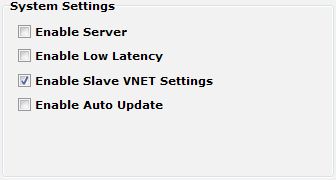
Figure 60: neoVI Explorer System Settings Pane
Available Firmware
This is an informational page that shows which firmware versions are available in this version of neoVI Explorer for various Intrepid products. Some devices have multiple firmware programs that control different aspects of their operation; in the case of the FIRE 2, these are called MCHIP and CCHIP.
You normally won’t need to look in this area, because as we’ll see in Section 5.3, neoVI Explorer shows you the current and available firmware versions for your FIRE 2 when you connect to it.
Updating Firmware
Firmware is essentially software that runs hardware, and is required to enable the many capabilities of your neoVI FIRE 2. New versions of firmware are created regularly by Intrepid’s engineers to implement new features and correct problems that have been identified.
If you have Enable Auto Update on–which is the default, and is recommended–then you don’t really need to worry about firmware updates. Each time you connect to your neoVI FIRE 2 in neoVI Explorer or go online with it in Vehicle Spy, the firmware will be checked, and if a newer version is available, the device will immediately be updated. You will see dialog boxes on the screen showing you the progress of this operation, which takes only a few seconds; an example is shown in Figure 61.
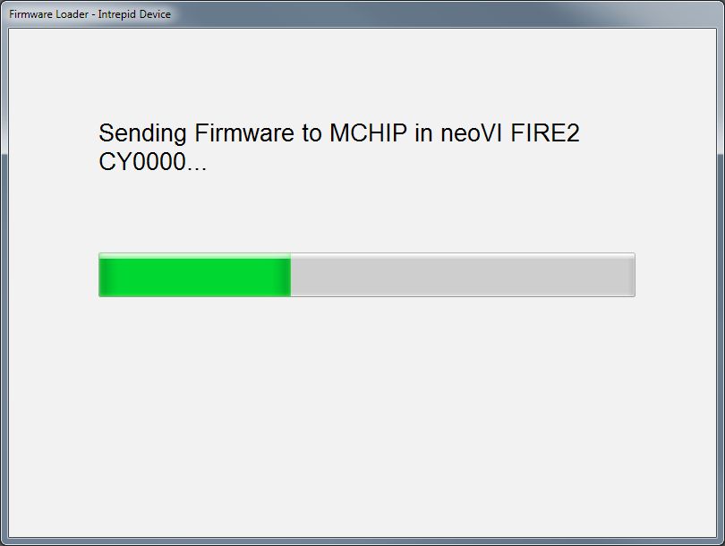
Figure 61: Firmware Download Message Box.
If you do not have automatic updates enabled, you control when your firmware is updated. When new firmware is available, you will be notified on the initial connection screen, as shown in Figure 62. Simply press the Manual Reflash button to update the firmware. Again, you will see messages as both the CCHIP and MCHIP firmware programs are sent to the device, and a message will appear in the message box on the right to tell you that the process has completed.
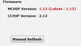
Figure 62: neoVI Explorer Firmware Message Box and Manual Reflash Button.
Note that while firmware updates are in progress, the device will be in bootloader mode, indicated by a “three green, one red” LED flash sequence. This will stop when the update is complete. Also, even if only one of the firmware components has a new version, both will be updated to ensure internal consistency in the FIRE 2.
5.3. General Settings and Product Details
These two areas of the neoVI FIRE 2’s parameter setup provide information about the device and allow you to perform a few basic maintenance tasks.
General Settings
After connecting to the device you will see basic information about it in the right-hand pane of the window (Figure 63):
The device’s serial number.
The firmware versions currently in the device, and an indication if new firmware is available.
A message showing that the hardware license for the device was recognized.
A current readout of the FIRE 2’s real-time clock.
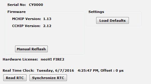
Figure 63: neoVI Explorer neoVI FIRE 2 General Settings
This information can be displayed again at any time by clicking the FIRE 2’s name in the explorer navigation window, or the General Settings entry immediately below it.
The versions of the MCHIP and CCHIP firmware for the FIRE 2 will each be shown in black if they match the firmware versions within neoVI Explorer. If they do not, the current version and the newest available version will be shown in red to help you notice that an update is available, as seen in Figure 62. Section 5.2 provides more information on firmware updates.
There are four buttons on this screen. Two of them, Load Defaults and Manual Reflash, were described in Section 5.2. The Read RTC button will reload the device’s internal time clock, while Synchronize RTC will set the device’s clock to the same value as that of the PC.
Product Details
This is an informational area that provides technical data on the FIRE 2’s hardware and internal setup. You will generally only need this if requested by Intrepid in order to facilitate support or troubleshooting. You can use the Copy To Clipboard button to copy all of the information to the Windows Clipboard, so you can then paste it into an email or file.
5.4. Standard CAN Networks (HS CAN 1-5 and MS CAN)
This area of neoVI Explorer is used to enable, disable and configure the six standard dual wire CAN networks in the FIRE 2: High Speed CAN channels 1 to 5 (HS CAN and HS CAN2-5) and the Medium Speed CAN channel (MS CAN). Each channel has an entry under the “CAN” group (which cannot be clicked itself). The current status of each channel is shown next to its name; a green checkmark indicates that the channel is enabled, while a red X means it is disabled. Figure 64 shows an example of the CAN channels area, with MS CAN and HS CAN4 currently disabled, and the other channels enabled.
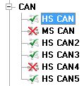
Figure 64: neoVI Explorer CAN Group.
All six of these channels have the same parameters, which can be configured using the controls in the right-hand pane; the default settings are shown in Figure 65.
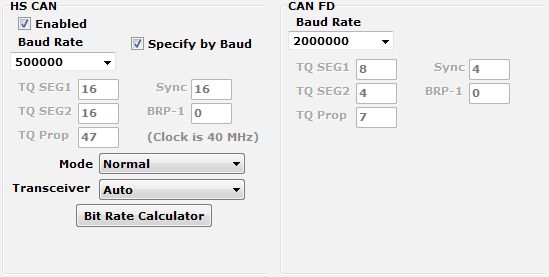
Figure 65: neoVI Explorer Standard CAN Parameters with Default Settings.
Enabled
Place a checkmark in this box to enable the channel, or clear the checkmark to disable it. When disabled, all of the other parameter controls are disabled (grayed out).
Specify by Baud
This is a master control that determines whether the operation of the channel is controlled by a numeric baud rate, or is calculated from lower-level timing parameters. When checked, the Baud Rate and CAN FD Baud Rate drop-down boxes are enabled and the various TQ, Sync and BRP-1 entries are disabled. When unchecked, this is reversed.
Specifying by baud rate is the default, and is recommended except for advanced users with special requirements.
Baud Rate
When Specify by Baud is selected, choose a baud rate for the channel from the drop-down box below. The default value is 500000.
CAN Timing Settings
When Specify by Baud is deselected, the operation of the CAN channel is based on these five settings: TQ SEG1, TQ SEG2, TQ Prop, Sync, BRP-1. These settings are for advanced users and normally should be left at their default values.
CAN FD Baud Rate
When Specify by Baud is selected, choose a baud rate for the data phase of CAN FD messages. The default value is 2000000.
CAN FD Timing Settings
When Specify by Baud is deselected, use these settings (TQ SEG1, TQ SEG2, TQ Prop, Sync, BRP-1) for the data phase of CAN FD messages. These parameters are for advanced users and normally should be left at their default values.
Mode
The operating mode of the channel; choose from one of these four options:
Normal: Normal operation (default).
Disable: Channel is disabled.
Listen Only: This channel only receives messages, with no transmissions, and also no error frames generated nor acknowledgments sent.
Transceiver
The operating mode of the CAN transceiver:
Auto: The transceiver is automatically controlled by the CAN logic for the channel (default).
Enabled: The transceiver is always enabled.
Disabled: The transceiver is disabled.
Bit Rate Calculator
Press this button to launch the Intrepid Bit Timing Calculator.
5.5. Selectable CAN Networks
The 7th and 8th of the FIRE 2’s CAN channels are user-selectable: they can be set as additional High Speed (dual wire) CAN channels (HS CAN6 and HS CAN7), as Low Speed Fault Tolerant CAN channels (LSFT CAN and LSFT CAN 2), or as Single Wire CAN channels (SW CAN and SW CAN 2). Both channels must be set to the same mode (so you cannot have HS CAN6 and SW CAN at the same time, for example). The selectable CAN channel group in neoVI Explorer can be seen in Figure 66.
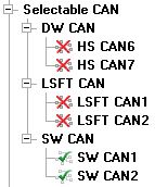
Figure 66: neoVI Explorer Selectable CAN Group.
Selectable CAN Mode
The master control for these channels can be found by clicking on Selectable CAN. On the right hand side you will find a drop-down box; choose DWCAN, LSFTCAN or SWCAN depending on which CAN variant you want for these two channels (Figure 67). SWCAN is the default.
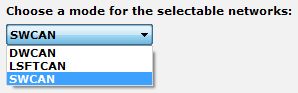
Figure 67: neoVI Explorer Selectable CAN Mode Control.
Based on your selection, neoVI Explorer will automatically enable the corresponding two channels in this group and disable the other four. You can manually override the enabled channels if, for example, you only want one of the two. You cannot, however, override the disabled channels, as they are physically disconnected within the device when your selection is made. (If you listen closely after changing the selection here and clicking Write Settings, you may even hear a relay click as the change is made in the hardware.)
DW CAN (HS CAN 6 / HS CAN 7)
When DWCAN is selected, two additional High Speed CAN channels are turned on. Their parameters are identical to the six standard CAN channels described in Section 5.4, and are configured in the same way.
LSFT CAN (LSFT CAN / LSFT CAN 2)
When LSFTCAN is selected these two channels are enabled. They have the same basic settings as the standard CAN channels (Figure 68), except that there are no CAN FD settings (since CAN FD is not supported on LSFT CAN). The default baud rate for LSFT CAN channels is 125000.
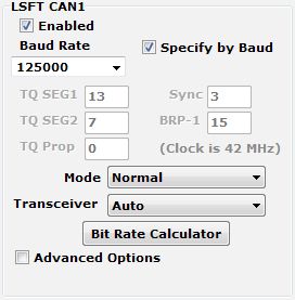
Figure 68: neoVI Explorer LSFT CAN Parameters with Default Settings.
SW CAN (SW CAN / SW CAN 2)
With SWCAN chosen under Selectable CAN, the Single Wire CAN channels are enabled. These have the same settings as the standard CAN channels, with the following changes (Figure 69):
No CAN FD section (CAN FD is not supported on these channels).
The Transceiver drop-down box has additional options: High Voltage and High Speed.
The High Speed Auto Switch option tells the channel to switch to high speed mode upon receipt of a specific message.
The default baud rate is 33333.
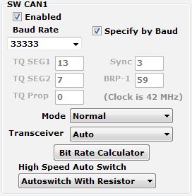
Figure 69: neoVI Explorer SW CAN Parameters with Default Settings.
5.6. LIN Networks (LIN1 to LIN4)
This section of the FIRE 2 explorer tree allows you to enable, disable and configure its four LIN channels, LIN1 to LIN4. Each channel has an entry under the “LIN” group (Figure 70). As with the CAN channels, a green checkmark indicates that a particular channel is enabled, while a red X means it is disabled.

Figure 70: neoVI Explorer LIN Group
All of these channels have the same parameters, which can be seen in Figure 71. In this image we have selected the Advanced Options checkbox to display its options (described below).
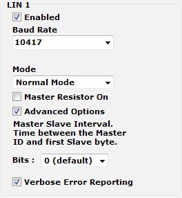
Figure 71: neoVI Explorer LIN Parameters, with Default Settings and Advanced Options Displayed.
Enabled
Place a checkmark in this box to enable the channel, or clear the checkmark to disable it. When disabled, all of the other parameter controls are disabled (grayed out).
Baud Rate
Select a baud rate for the channel; the default is 10417.
Mode
This option is currently not used and should be left at the default of “Normal Mode”.
Master Resistor On
Enable this option for the neoVI FIRE 2 to act as the master on the specified LIN bus.
Advanced Options
Click this checkbox to reveal two additional options:
Master Slave Interval: The time between the master ID and the first slave byte, in bits (default 0).
Verbose Error Reporting: When checked, break errors and other error messages from the LIN driver are displayed.
5.7. MISC IO
This section contains parameters controlling the neoVI FIRE 2’s miscellaneous I/O channels. Reporting parameters can be found within the main “MISC IO” entry, while others are contained in two subordinate panels in the explorer navigation tree.
Reporting Parameters
These parameters allow you to control reporting related to miscellaneous I/O channels (Figure 72):
Report on Period: Enable this option and select a time interval to turn on periodic reporting.
Report GPS Coordinates: Check this box to enable GPS support.
Report on Change: Check the boxes of the channels for which you want detected value changes to trigger a report.
Analog Threshold: Set the analog threshold percentage value (default is 10%).
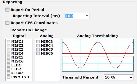
Figure 72: neoVI Explorer MISC I/O Reporting Parameters
Initial Values
In this section you can select the operating mode of each I/O channel (Figure 73). Each can be set as a digital input, as a digital output that is initially off, or as a digital output that is initially on.
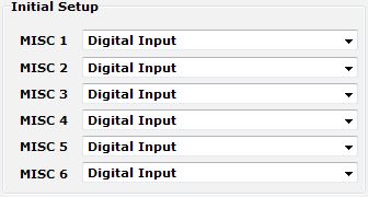
Figure 73: neoVI Explorer MISC I/O Initial Channel Configuration
Advanced Analog Settings
The one option here allows you to control how often each channel is sampled.
5.8. Other Parameters
In addition to the network-specific parameters described above, there are a number of additional option sets that you can use to tailor the operation of your FIRE 2 (Figure 74).
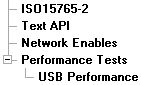
Figure 74: neoVI Explorer Additional Parameter Groups.
ISO 15765-2
This page contains one setting: IFS Shift Register (Figure 75). Changing this from its default value of 0 causes time to be added to the Inner Frame Spacing of USDT frames transmitted by CoreMini scripts running in the FIRE 2. The number entered is multiplied by 6.4 µs to determine the time offset. The allowed range is -1563 to 1563.
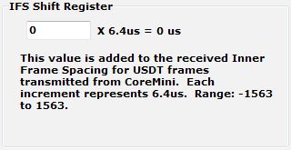
Figure 75: neoVI Explorer IFS Shift Register Parameter for ISO 15765-2.
Text API
These parameters control the operation of the text API that can be used to operate the neoVI FIRE 2 using third party software. Please contact Intrepid if you require assistance with using the API.
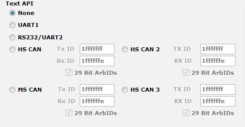
Figure 76: neoVI Explorer Text API Parameters.
Network Enables
This area provides more options for controlling the enabling and disabling of individual networks within the FIRE 2 (Figure 77). The main display contains a scrollable list with checkboxes that can be set or unset to enable or disable each network. These are equivalent to the Enable checkboxes found in the parameter areas for the corresponding networks.
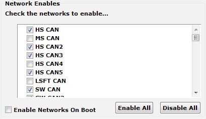
Figure 77: neoVI Explorer Network Enable/Disable Parameters.
Enable Networks on Boot
Normally, the neoVI FIRE 2 will not acknowledge messages on a network unless it is online with that network or running a CoreMini script. When this option is enabled, the device always acknowledges frames on all enabled networks.
Enable All
Enables all networks. Note that this may include enabling networks that are mutually exclusive (such as SW CAN and LSFT CAN). If you use this option, be sure to disable networks that should be off, so the device remains in a valid configuration.
Disable All
Disables all networks.
Performance Tests / USB Performance
Under Performance Tests is a single area called USB Performance. Here you will find a test to check the performance of the FIRE 2’s USB connection (Figure 78). When Enable Performance Blast Test is checked, the FIRE 2 sends high-speed traffic over the USB connection to the PC.
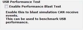
Figure 78: neoVI Explorer USB Performance Test.