3. A Tour of RAD-Pluto Hardware
Before learning how to configure and set up the device, let’s examine the device from all sides to understand all of its interfaces and status indicators.
3.1. Label and Status Indicators
3.1.1. LED Indicators
The function of the LED indicators is defined by which membrane button is active (flashing). The color of the active membrane button indicates the following states of the device:
Color |
State |
|---|---|
Orange |
Powered |
White |
USB Connected |
Blue/Green Flash |
Online with VSPY |
Magenta |
Script Running |
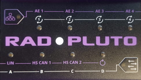
3.1.2. Purple Membrane Button
Pressing the purple membrane button activates the purple labels which indicate the status of the networks.
AE1-AE4: Link Status of Automotive Ethernet Ports 1-4
LIN: LIN Status
HSCAN 1-2 Status
The CAN and LIN network statuses are indicated with the following colors:
Color |
State |
|---|---|
Blue |
Message Received |
Green |
Message Transmitted |
Red |
Network Errors |
3.1.3. White Membrane Button
Pressing the white membrane button activates the white labels which are reserved for future use.
3.2. Connector Interfaces
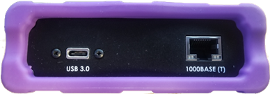
3.2.1. USB C (Left):
This connection serves 3 purposes
Device power from a USB 3.0 rated port. (1A)
GigE / USB Bridge (When enabled)
Data Connection for VSPY 3 and configuration using neoVI Explorer
3.2.2. RJ-45 Port (Right):
An industry-standard conventional Ethernet jack. This interface shares one port of the integral switch with AE-4 (100BASE-T1). Only one interface can be active at a time.
The RJ-45 port has a pair of integrated LEDs that provide information about the RAD-Pluto’s conventional Ethernet connection:
Link LED (Green): Indicates that a valid link has been established between the RAD- Moon and another 10/100/1000 Ethernet device.
Activity LED (Orange): Flashes when traffic passes in either direction over the attached Ethernet cable.
In normal operation you should see the Link LED always on, and the Activity LED flashing at a variable rate, with faster flashing meaning that more data is being transferred.
The RAD-Pluto’s standard 10/100/1000 Ethernet connection will automatically negotiate to match the speed of the Ethernet device to which it is attached. In most cases it will run at 1000 Mb/s, though it will support connection to a device that runs at 10 or 100 Mb/s.
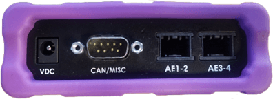
3.2.3. VDC (Left):
The device can be powered using the DC supply provided with your purchase. If an alternate DC supply is used, it must be within the range of 5V-40V with a current capacity of 1 Amp, or the device may malfunction or be permanently damaged.
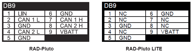
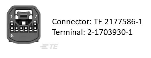
3.2.4. CAN/MISC (Center):