5. The neoVI Explorer Configuration Utility
5.1. Starting and Using neoVI Explorer
The neoVI Explorer utility allows you to connect to, manage and configure all of your Intrepid Control Systems hardware. It is supplied both as an integrated feature of Vehicle Spy, and as a standalone program. This section will describe general features and the basics of using neoVI Explorer, so you will understand the utility when we get into settings specific to your device.
5.1.1. Starting neoVI Explorer from within Vehicle Spy
There are several ways to open neoVI Explorer from within VSpy. These are probably the two easiest, since they are accessible at all times:
Menu Item: Click the Setup menu and then select Hardware.
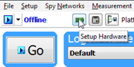
Hardware Setup Button: Click the button located in the main Vehicle Spy toolbar just under its menu (Figure below).
Note
neoVI Explorer cannot be launched when Vehicle Spy is online (even if in simulation mode). If you attempt to do so, VSpy will prompt you to either go offline and launch neoVI Explorer, or remain online and return to Vehicle Spy.
5.1.2. Starting neoVI Explorer as a Standalone Program
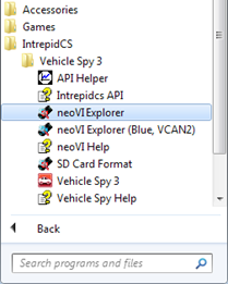
If you want to work with your device without opening Vehicle Spy, you can launch neoVI Explorer directly. Open the Start Menu, navigate to the IntrepidCS folder, then under the Vehicle Spy 3 sub-folder, select neoVI Explorer (Figure below).
5.1.3. Starting neoVI Explorer as a Standalone Program (API Kit Installed)
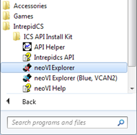
If you installed the API kit and support files instead of Vehicle Spy, you can run neoVI Explorer from the Start Menu using the same basic process as described above. The only difference is the name of the sub-folder, so you will navigate to the IntrepidCS folder, then open the ICS API Install Kit sub-folder, and finally select neoVI Explorer (Figure below).
5.2. Interfacing with your device
5.2.1. Connecting to your device
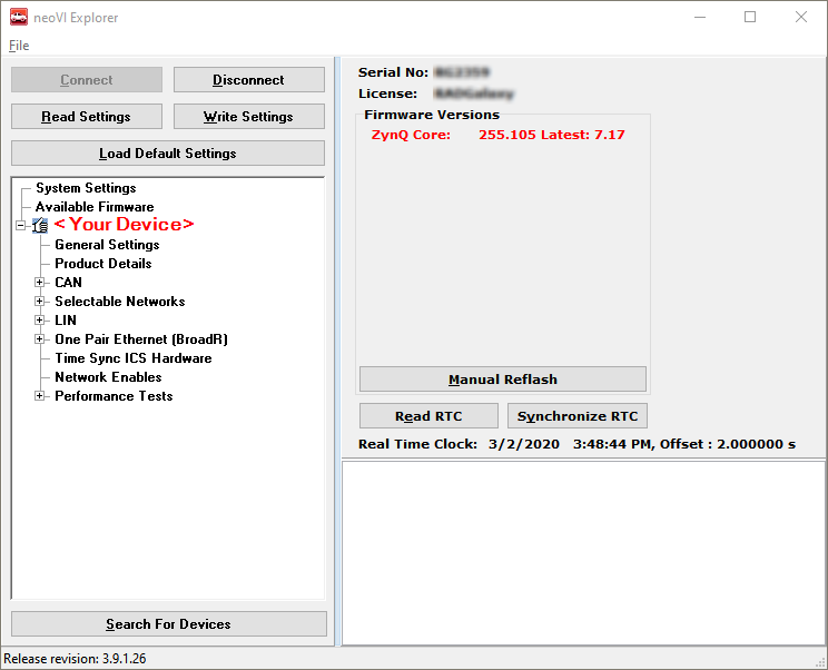
When neoVI Explorer loads, it will start up with the first hardware device it can find selected in the menu pane on the left. You should see your device listed here, along with its serial number. If you don’t see the device to be connected, but do see other Intrepid devices, be sure to scroll down to look for it. If it is still not visible, this means its drivers have not been installed correctly, it is not powered properly, or there is a problem with the USB connection.
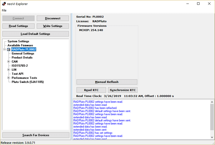
To manage your device, click on its entry in the navigation pane (if it is not already highlighted) and then press the Connect button. After successfully connecting to the device, you will see a “thumbs up” icon next to the device’s name, and checkmarks will appear next to currently-enabled networks in the explorer area on the left. You should also see a message in the message box on the right saying “<Your Device and Serial Number> settings have been read”. This tells you that neoVI Explorer has loaded the current settings from the unit.
The screen as a whole should appear similar to the screen shown below (but note that the device and version number shown below may be different).
Searching for Devices
If you attach new hardware to your PC after starting neoVI Explorer, press the Search For Devices button at the bottom left of the dialog box to prompt the program to scan for new hardware you can manage.
Note
It is possible to click on various parameter groups at any time, but they will not show valid date until you connect to the device. Remember also to connect to the device before making changes, or they will be erased when you do connect to the settings in the hardware are
5.2.2. Device Configuration
Writing and Reloading Settings
To avoid potential problems, neoVI Explorer will not save any changes to device parameters until you instruct it to do so. This is done by pressing the Write Settings button, which will update the parameters within the firmware in your device. If you make changes you do not want to keep, pressing the Read Settings button will reload the settings stored in the device, wiping out any modifications made in neoVI Explorer that had not yet been saved.
Reloading Device Defaults
To return all settings to factory defaults, press the Load Default Settings button. This is convenient if many changes have been made and written to the firmware in the past, and you want to start over with a clean slate. Note that pressing this button actually writes the defaults to the device first, and then reloads them automatically, so you do not need to also press Write Settings. You will see messages in the message area telling you that defaults have been sent to the device and then read from it.
Disconnecting from the device
Press the Disconnect button to tell neoVI Explorer that you are done working with the device. This step is actually optional, because neoVI Explorer will disconnect from any connected devices when you exit the program.
Exiting neoVI Explorer
Like any Windows program, you can close neoVI Explorer by clicking the “X” in the top right corner, or pressing the Alt+F4 key combination.
5.3. System Settings and Firmware Updates
The top two entries in the explorer window on the left side of neoVI Explorer contain system- wide settings that apply to all hardware devices, and information related to firmware updates.
5.3.1. System Settings
In the top branch of the tree in the left pane of neoVI Explorer you will see several settings that you can enable or disable:
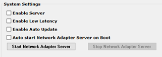
Enable Server: Turns on the neoVI Server feature, a background program that allows your hardware to be used by multiple applications at the same time.
Enable Low Latency: This is an advanced setting for applications where fast response is needed after transmission.
Enable Auto Update: When enabled, both neoVI Explorer and Vehicle Spy will automatically update firmware. If this box is not checked, firmware must be updated manually. (See below for details.)
Network Adapter Server: This is a feature that is used with Intrepid products having Ethernet ports. (It may not apply to your device.) With This feature enabled, the Ethernet ports on your Intrepid hardware will enumerate as network interfaces in the operating system of your host computer. This server can be started and stopped in this window. There is also a checkbox to configure the server to start after booting your computer.
5.3.2. Available Firmware
This is an informational page that shows which firmware versions are available in this version of neoVI Explorer for various Intrepid products. Note that some devices have multiple firmware programs that control different aspects of their operation; You normally won’t need to look in this area, because as we’ll see in Section , neoVI Explorer shows you the current and available firmware versions for your device when you connect to it.
5.3.3. Automatic and Manual Firmware Updates
Warning
While your device may appear to operate with incompatible firmware, proper and reliable operation cannot be guaranteed unless the version of firmware matches what is listed in Vehicle Spy
Firmware is essentially software that runs hardware and is required to enable the many capabilities of your device. New versions of firmware are created regularly by Intrepid’s engineers to implement new features and correct problems that have been identified.
If you have Enable Auto Update on—which is the default, and is recommended—then you don’t really need to worry about firmware updates. Each time you connect to your device in neoVI Explorer or go online with it in Vehicle Spy, the firmware will be checked, and if a newer version is available, the device will immediately be updated. If you do not have automatic updates enabled, you control when your firmware is updated. When new firmware is available, you will be notified on the initial connection screen, as shown below. Simply press the Manual Reflash button to update the firmware.
5.3.4. The Firmware Update Process
During the firmware update process, the device will be placed into bootloader mode, indicated by all LEDs on the top label flashing synchronously. Normal LED flash patterns will resume when the update is complete and the device reboots. You will see a dialog box on the screen showing you the progress of the firmware update operation. an example is shown below. You will also see messages in the message box on the right side of neoVI Explorer as the firmware program is sent to the device. When the process is complete the dialog box will disappear and another message will appear in neoVI Explorer to confirm that the update has finished. If you receive any error messages or experience any other problems updating your device’s firmware, please contact Intrepid for assistance.
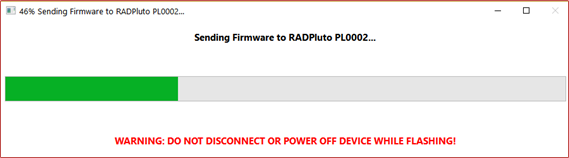
Warning
Please take heed of the warning on the firmware update dialog box: leave the device connected and powered on for the entire firmware update process to avoid possible problems with the device.
5.4. General Settings and Product Details
These two areas of the device’s parameter setup provide information about the device and allow you to perform a few basic maintenance tasks.
5.4.1. General Settings
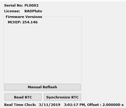
After connecting to the device you will see basic information about it in the right-hand pane of the window:
The device’s serial number.
The firmware versions currently in the device, and an indication if new firmware is available.
A message showing that the hardware license for the device was recognized.
A current readout of the device’s real-time clock.
This information can be displayed again at any time by clicking the device’s name in the explorer navigation window, or the General Settings entry immediately below it.
The version(s) of the firmware for the device will be shown in black if it matches the firmware version within neoVI Explorer. If not, the current version and the newest available version will be shown in red to help you notice that an update is available. (See the previous section for more about the update process.)
There are three buttons on this screen.
Manual Reflash (described in the previous section)
Read RTC button will reload the device’s internal time clock
Synchronize RTC will set the device’s clock to the same value as that of the PC.
5.4.2. Product Details
This is an informational area that provides technical data on the devices’s hardware and internal setup. You will generally only need this if requested by Intrepid in order to facilitate support or troubleshooting. You can use the Copy To Clipboard button to copy all of the information to the Windows Clipboard, so you can then paste it into an email or file.
5.5. CAN Network Settings
5.5.1. CAN Networks
This area of neoVI Explorer is used to enable, disable and configure the High Speed CAN channels. Each channel has an entry under the “CAN” group (which cannot be clicked itself). The current status of each channel is shown next to its name; a green checkmark indicates that the channel is enabled, while a red X means it is disabled. The figure below shows an example of the CAN channels area, with HS CAN enabled and HS CAN2 disabled.

All of the CAN channels have the same parameters, which can be configured using the controls in the right-hand pane; the default settings are shown below.
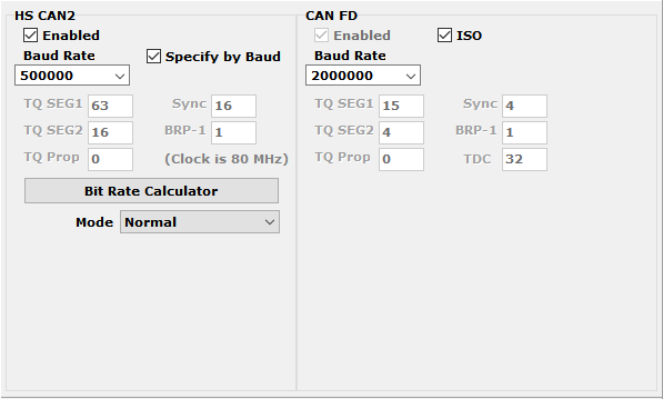
Enabled: Place a checkmark in this box to enable the channel, or clear the checkmark to disable it. When disabled, all of the other parameter controls are disabled (grayed out).
Specify by Baud: This is a master control that determines whether the operation of the channel is controlled by a numeric baud rate, or is calculated from lower-level timing parameters. When checked, the Baud Rate and CAN FD Baud Rate drop-down boxes are enabled and the various TQ, Sync and BRP-1 entries are disabled. When unchecked, this is reversed. Specifying by baud rate is the default, and is recommended except for advanced users with special requirements.
Baud Rate: When Specify by Baud is selected, choose a baud rate for the channel from the drop-down box below. The default value is 500000.
CAN Timing Settings: When Specify by Baud is deselected, the operation of the CAN channel is based on these five settings: TQ SEG1, TQ SEG2, TQ Prop, Sync, BRP-1. These settings are for advanced users and normally should be left at their default values.
CAN FD Baud Rate: When Specify by Baud is selected, choose a baud rate for the data phase of CAN FD messages. The default value is 2000000.
CAN FD Timing Settings: When Specify by Baud is deselected, use these settings (TQ SEG1, TQ SEG2, TQ Prop, Sync, BRP-1) for the data phase of CAN FD messages. These parameters are for advanced users and normally should be left at their default values.
Mode: The operating mode of the channel; choose from one of these four options: * Normal: Normal operation (default). * Disable: Channel is disabled. * Listen Only: This channel only receives messages, with no transmissions, and also no error frames generated nor acknowledgments sent.
Bit Rate Calculator: Press this button to launch the Intrepid Bit Timing Calculator.
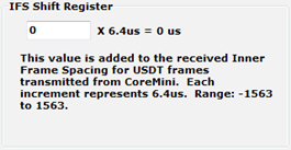
5.5.2. ISO15765-2:
This page contains one setting: IFS Shift Register (shown below). Changing this from its default value of 0 causes time to be added to the Inner Frame Spacing of USDT frames transmitted by CoreMini scripts running in the FIRE 2. The number entered is multiplied by 6.4 µs to determine the time offset. The allowed range is -1563 to 1563.
5.6. LIN Network Settings
This section of your device’s explorer tree allows you to enable, disable and configure its LIN channels. Each channel has an entry under the “LIN” group (seen below). As with the CAN channels, a green checkmark indicates that a particular channel is enabled, while a red X means it is disabled.

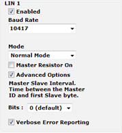
All of these channels have the same parameters, which can be seen below. In this image we have selected the Advanced Options checkbox to display its options (described below).
<div style=”page-break-after: always;”></div>
Enabled: Place a checkmark in this box to enable the channel, or clear the checkmark to disable it. When disabled, all of the other parameter controls are disabled (grayed out).
Baud Rate: Select a baud rate for the channel; the default is 10417.
Mode: This option is currently not used and should be left at the default of “Normal Mode”.
Master Resistor On: Enable this option for your device to act as the master on the specified LIN bus.
Advanced Options: Click this checkbox to reveal two additional options:
Master Slave Interval: The time between the master ID and the first slave byte, in bits (default 0).
Verbose Error Reporting: When checked, break errors and other error messages from the LIN driver are displayed.
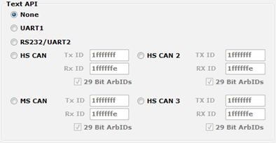
5.7. Text API
These parameters control the operation of the text API that can be used to operate the neoVI FIRE 2 using third party software. Please contact Intrepid if you require assistance with using the API.
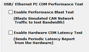
5.8. Performance Tests
The following are tests which can be used to characterize the bandwidth and latency between ICS hardware and its host computer. If you suspect you have a problem with either of these, our customer support would be happy to help resolve it. Reference the end of this document for contact information.
5.9. gPTP Time Synchronization
RAD-Pluto supports Generalized Precision Time Protocol as defined in IEEE 802.1AS. It can be configured to use the Standard profile or the Automotive profile as defined by the Avnu Alliance.
Typically the timestamp Physical Hardware Clock (PHC) of your device is synchronized with a host computer when connected. In cases where it is desireable for this clock to be synchronized with another clock source, gPTP can be enabled. The clock is automatically synchronized to Epoch Time when enabled and it is connected to a gPTP grandmaster.
If all of the ports enabled for gPTP on the RAD-Pluto are configured as master ports (with no slave ports), RAD-Pluto will act as the Grandmaster and use its PHC as the Grandmaster Time.
Note
Erratic behavior may be observed if the Epoch Time of logged messages is prior to 1/1/2007.
The gPTP profile can be set to either Automotive (AVNU) or Standard Profile using the drop down menu at the top of the gPTP configuration tab.
5.9.1. Common Settings
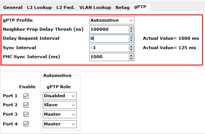
gPTP Profile |
Automotive: AVNU defined profile |
Standard |
|
Neighbor Prop Delay Threshold |
Device will be identified as non-AS Capable if pDelay exceeds this value Default 800, but increased to 100000 to insure latency of active tap does not impact ability to connect stream. Can be set as high as 10000000 for the purposes of certain AVNU testing |
Delay Request Interval |
Period of Pdelay_Request |
Sync Interval |
Period of Sync/Followup messages |
PHC Sync Interval |
Period the PHC (Physical Hardware Clock) is synchronized with the gPTP clock value. (This is the clock used for timestamping network messages.) |
Announce Interval |
Period of BCMA Announce message (Standard profile only) |
Note
The interval of Delay Request Interval, Sync Interval, and Announce Interval are calculated using the value entered as follows:
Value = log2(Interval in Seconds)
Min =-5 / Max =22
5.9.2. Automotive Profile Settings (Avnu)
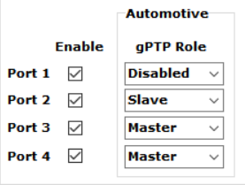
Enable |
Enables gPTP for the specified port |
gPTP Role |
Master |
Slave |
|
Passive |
|
Slave |
|
Disabled |
5.9.3. Standard Profile Settings
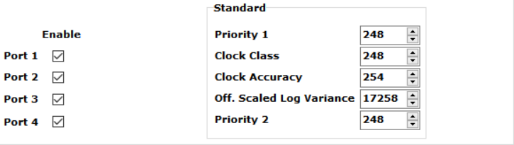
Enable |
Enables gPTP for the specified port |
Grandmaster Credentials (Reference IEEE-1588-2008 for attribute details) |
Priority 1: 0-255, lower value = higher priority |
Clock Class: Attribute defining a clock’s TAI traceability |
|
Clock Accuracy |
|
Offset Scaled Log Variance: Attribute defining the stability of a clock |
|
Priority 2: 0-255, lower value = higher priority |
5.10. SJA1105 Switch Configuration
5.10.1. General Settings
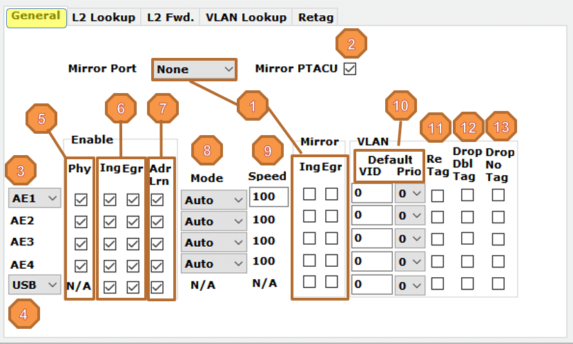
Each port can be configured to forward ingress and/or egress frames to the Mirror Port.
When enabled, the Mirror Port can be changed dynamically by the CoreMini Processor
Port 1 PHY Selection between 100BASE-T1 and 1000BASE-T
Port 5 connection selection between USB Bridge and CoreMini Processor
Each PHY can be independently enabled/disabled.
The Ingress and Egress of each port can be independently enabled/disabled.
The L2 Address learning can be disabled by port in the event a static L2 Address table is used.
Link Mode: Master/Slave/Auto
Link Speed can be configured for the 1000BASE-T only.
Default VID and PCP can be defined to be added to untagged ingressing frames. VLAN’s present here must also be defined in the VLAN table with the flag of the port set in VMEMB_PORT to avoid VLAN conflicts. Frames that ingress already containing a VLAN tag are not changed unless re-tagging is enabled.
When enabled, all ingressing frames already containing a VLAN tag are re-tagged with the default VID. The PCP is not changed.
When enabled, ingressing frames with nested VLAN tags are dropped. Note that this filters for frames having the identifier 0x88A8, and not the deprecated value 0x9100.
When enabled, ingressing frames with no VLAN tag are dropped.
5.10.2. L2 Address Table

Entries in this table define how ingress frames are forwarded to other ports for egress based on MAC address and an optional VLAN_ID.
Dest_Ports: When enabled, frames with the given MAC/VLAN be forwarded to that port.
Enf_Port: When enabled, ingress frames will be dropped if there is not a table entry associating the MAC/VID and that port. (e.g. to block traffic being spoofed with that MAC address on other switch ports)
Learned: When checked, the entry is a learned entry and will be not be persistent after boot. (This checkbox cannot be edited)
Add: Add an entry to this table
Delete: Delete the selected entry to this table
Delete All: Delete all entries in table
Note
Writing any settings to the RAD-Pluto purges the learned entries in the L2 table. A static entry overrides any learned entry.
5.10.3. L2 Forwarding Table
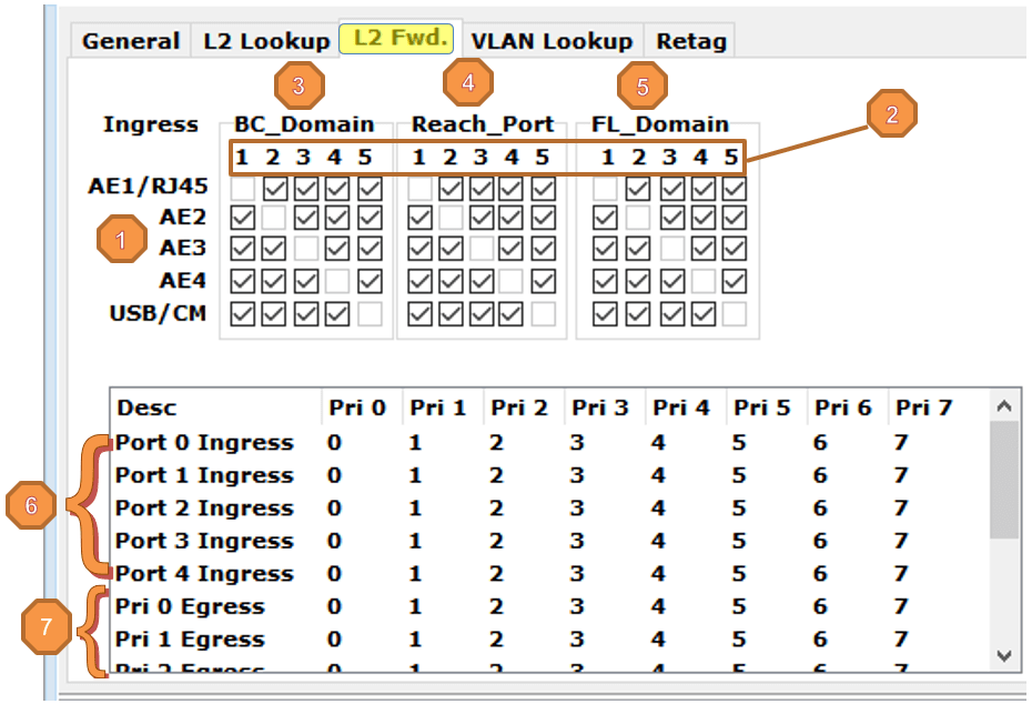
Each row defines how frames are forwarded after ingress on that port.
Egress rules for each port are defined in the columns.
BC_Domain: By default, a broadcast frames from any port will be forwarded to the other 4 ports of the switch. Unchecking a box in one of the columns will block broadcast frames to that port from that row’s ingress port.
Reach_Port: Each check box enables forwarding of frames from that ingress port to the egress port if the L2 Address Table associates that port with the destination MAC address of the frame. Disabling ports in this table is also known as implementing “Port Based VLAN’s”
FL_Domain: Each checkbox enables the forwarding of frames with unknown destination MAC Addresses. (Port Flooding)
Ingress VLAN Priority Remapping: Each ingress port is capable of changing the priority of an ingressing frame before it proceeds to the egress stage. This table defines this one-for-one remapping for each ingress port.
Egress VLAN Priority Mapping to physical priority queues
5.10.4. VLAN Lookup Table
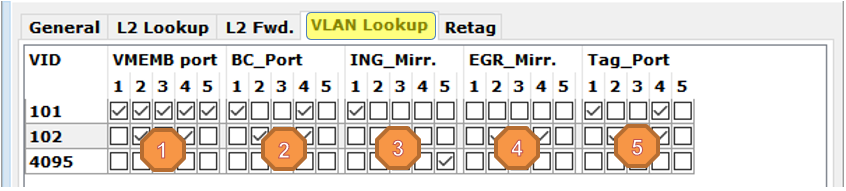
VMEMB_Port: Enables ingress for frames containing the VID on each checked port. (defining which ports are members of that particular vlan)
BC_Port: Enables egress for Broadcast frames containing the VID on each checked port.
ING_Mirr: Ingress frames on enabled ports having the VID will be forwarded to the mirror port.
EGR_Mirr: Egress frames on enabled ports having the VID will be forwarded to the mirror port.
Tag_Port: If unchecked, the VLAN tag will be stripped on egress for that port.
5.10.5. VLAN Retagging Table
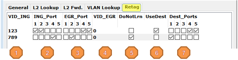
This feature is used to create copies of tagged frames for debugging and monitoring. Each copied frame will be retagged and forwarded as if it were received on the original ingress port. This table is limited to 32 entries.
VID_ING: Each entry specifies a VID which can trigger the copying, retagging, and forwarding of the frame as defined in the contents of the table.
ING_Port: On enabled ports, Ingress frames tagged with VID In are copied, retagged, and forwarded. Only one copy is made regardless of if it is forwarded to
EGR_Port: On enabled ports, Egress frames tagged with VID In are copied, retagged, and forwarded.
VID_EGR: VID used on retagged frame
DoNotLrn: Disables address learning for frames having a VID matching the VID Out
UseDest: Enables forwarding of frames containing VID Out to ports defined in Dest Ports.
Dest_Ports: Defines ports which are to be forwarded any frame containing VID Out. This includes copied/retagged frames as well as ingress frames having this VID. This bypasses all other forwarding rules. (Enabled by UseDest)