6. Core Features
In this chapter we show you just some of the many applications of your device. Each of section contains an example application, and where possible,step-by-step instructions are provided for those who wish to duplicate the results on their own device. The goal of this chapter is specifically to assist those who are new to Intrepid hardware and software, and so simplified examples are provided. Advanced users may wish to skim or even skip to the last 2 examples. The examples use Intrepid’s Vehicle Spy, the ideal tool for working with your device. Due to the complexity of Vehicle Spy, we only describe the basics necessary for the examples; for full details on this powerful software tool, please see the separate Vehicle Spy documentation.
Note
Intrepid makes a wide variety of hardware, each having their own mix of different networks intergrated. Your device may not have all of the networks and capabilities in the following section. If you are unsure of your device’s features, reference Introduction and Overview or constact icssupport@intrepidcs.com
6.1. Interfacing with Vehicle Networks
6.1.1. Monitoring CAN/CAN-FD and Ethernet
Once the device is configured correctly, this example will show how your device can monitor CAN traffic on a bench network using Vehicle Spy 3.
Assuming that your network already has CAN messages being transmitted by other devices, we can monitor that traffic with these simple steps:
Launch Vehicle Spy: Start Vehicle Spy by double-clicking its icon or selecting it from the Windows Start Menu.
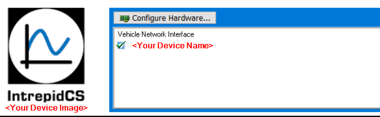
Select your device: On the Logon Screen, select your device if it does not already have a green checkmark next to it. To do so, right-click the device name and choose Select Hardware.
Go Online: Press the blue button in the top left corner of Vehicle Spy.
The program will go online and automatically switch to Messages View, showing you the incoming traffic. The example below shows CAN messages that are being transmitted to your device. By default, CAN messages sharing the same Arbitration ID will be shown with the latest update of data bytes available (Static View). Similarly, Ethernet messages are grouped based on Source Address and Ethertype. If you prefer to see the messages in chronological order, press the Scroll button located just above the message display.
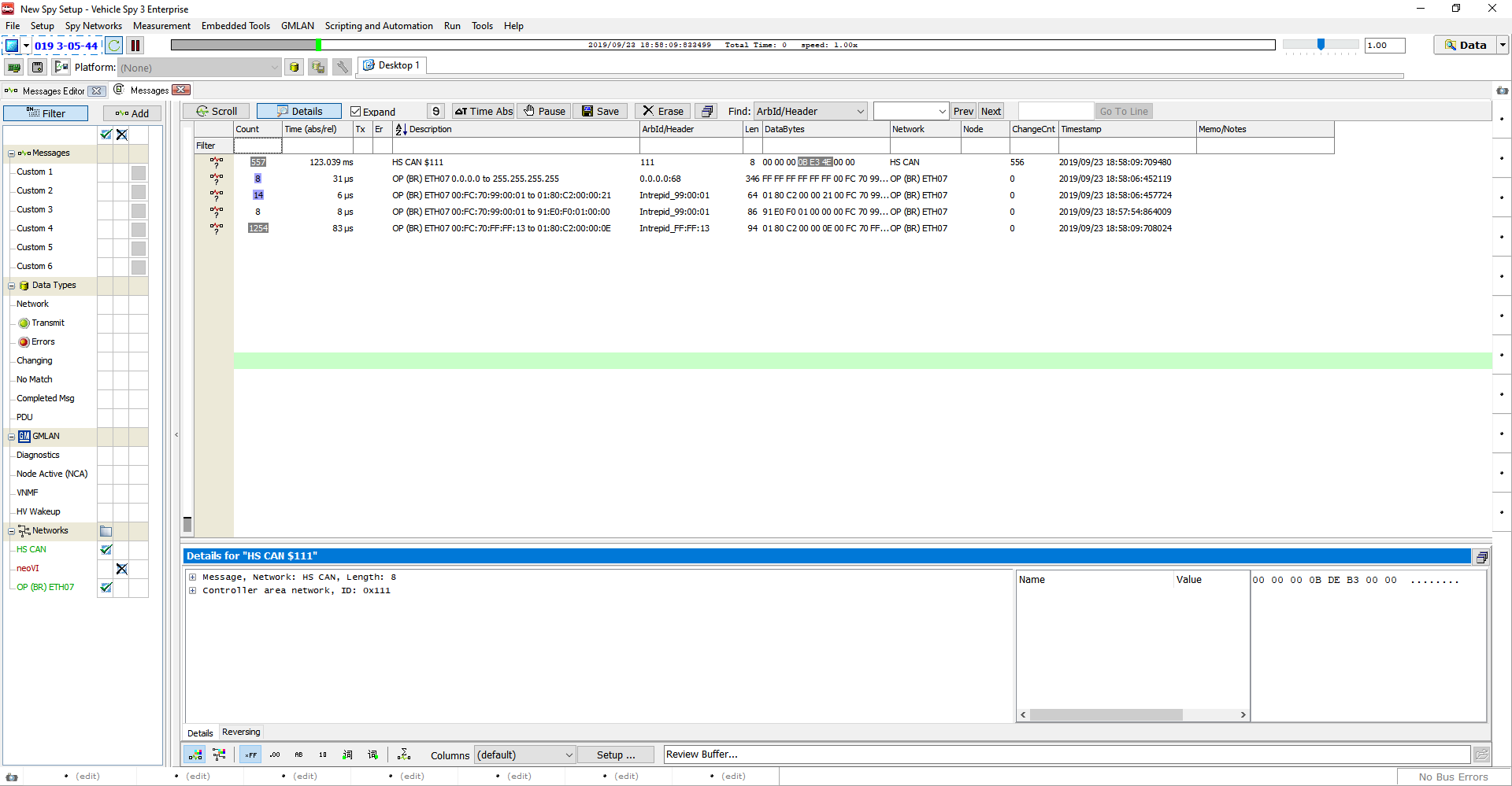
Notice that the messages are shown in their raw form, with some header information and data bytes. If you have a database matching the message traffic being monitored, you can load it into a platform and Vehicle Spy will decode the messages and show the signals within each. For details on how to accomplish this, please consult the Vehicle Spy documentation.
6.1.2. Transmitting on CAN/CAN-FD and Ethernet
In addition to monitoring network traffic with your device, we can also easily generate and transmit traffic of our own. We’ll show how this is done by creating and then transmitting am custom CAN message on the HS CAN channel.
Creating a CAN Transmit Message
Make sure your device is connected to your vehicle network. Then follow these steps to create and transmit a message:
Launch Vehicle Spy: Start Vehicle Spy by double-clicking its icon or selecting it from the Windows Start Menu.
Select your device: On the Logon Screen, selec your device if it is not already selected: right-click the device name and choose Select Hardware.
Load Messages Editor: Select Messages Editor from the Spy Networks menu.
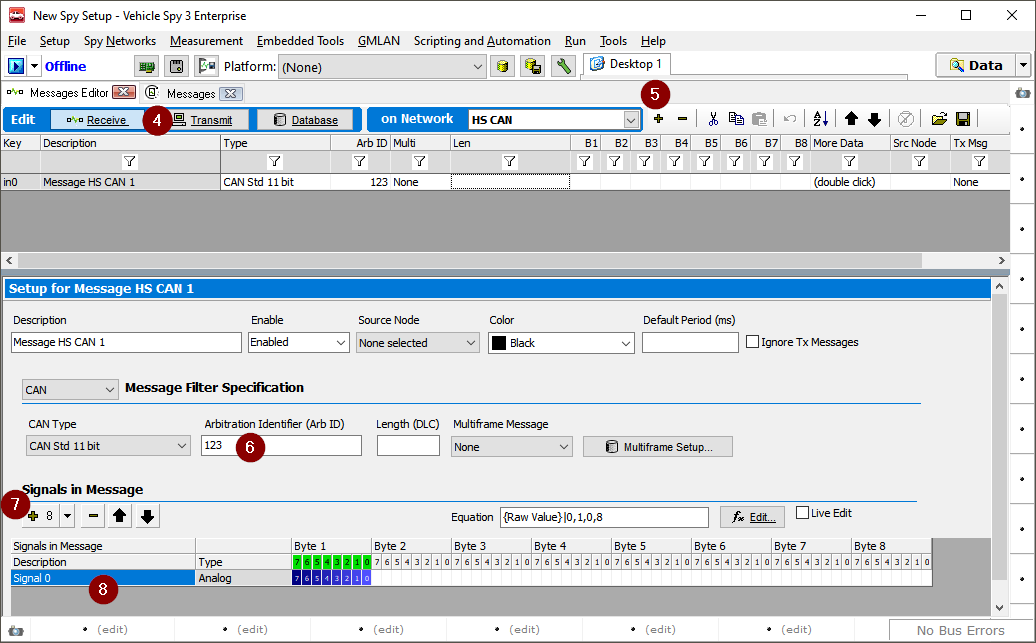
Select Transmit Messages: Click the Transmit button, found in the blue bar.
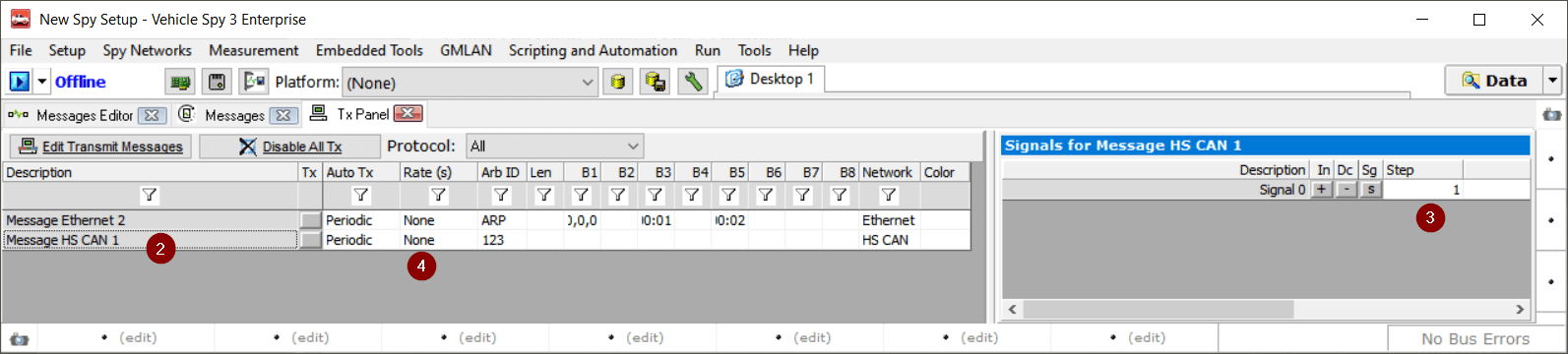
Create Transmit Message: To the right of the drop-down box that currently shows “HS CAN”, click the button. Vehicle Spy will generate a new HS CAN transmit message called “Tx Message HS CAN 1”, preset with default values.
Set Message to Arbitration ID 123: Under the Arb ID column for the message, enter the value “123”.
Add Message Signal: In the middle of the screen, find “Signals in Message; just below this click the button. A signal called Signal is created.
Rename Message Signal: Under the Description column, double-click Signal and change the name to Engine Speed.
Creating an Ethernet Transmit Message
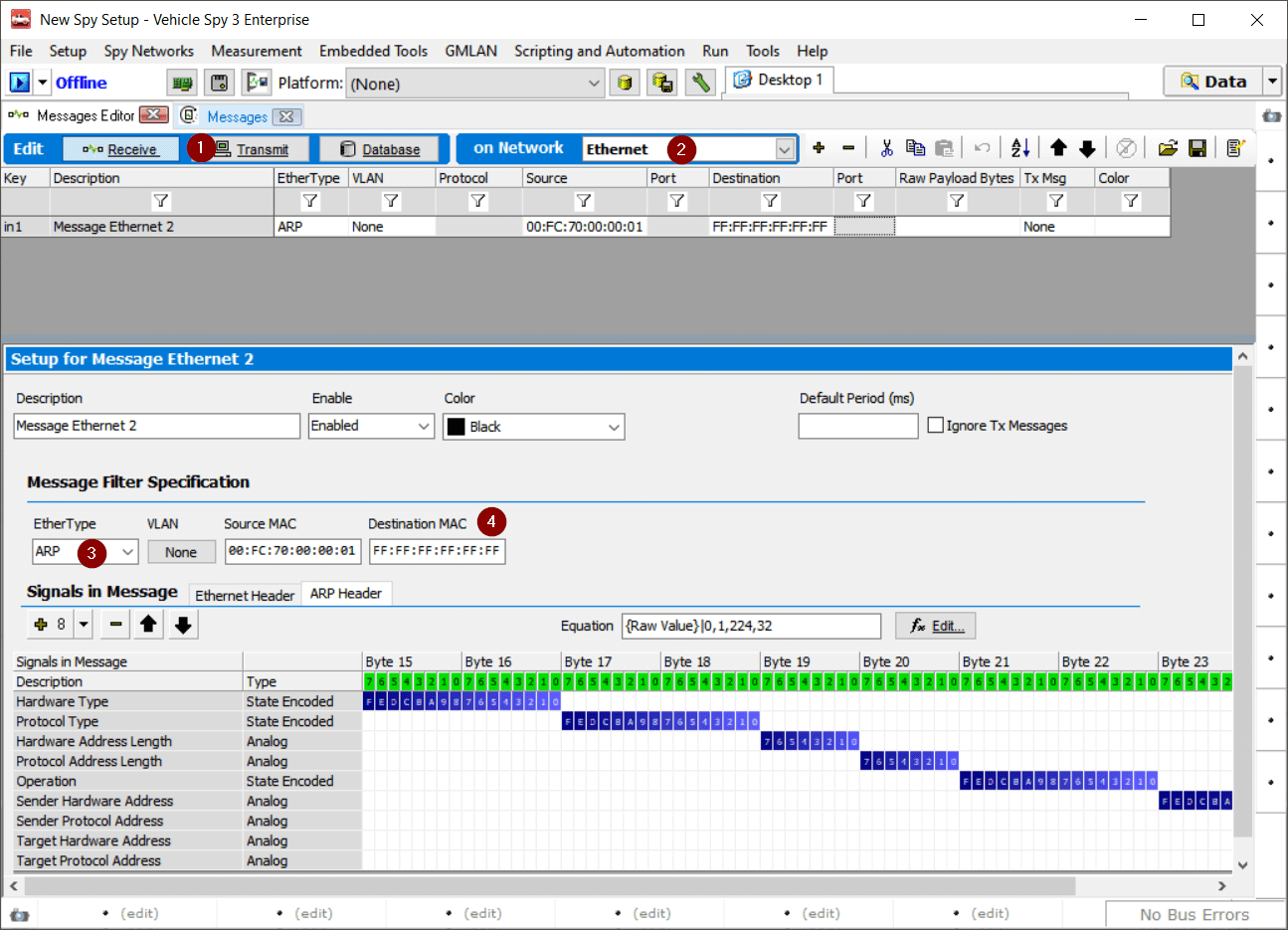
Select Transmit Messages: Click the Transmit button, found in the blue bar.
Change to Ethernet transmit table: Select “Ethernet” from the “on Network” drop-down menu
Change Ethertype: Select “ARP” from the Ethertype drop-down menu
Change the Detination Address: Use a broadcast address. (FF:FF:FF:FF:FF:FF)
Transmitting on CAN and Ethernet
We’ll now use the Tx Panel to specify a simple static value to send in that signal, and then instruct Vehicle Spy to transmit the message periodically.
Load Tx Panel: Select Tx Panel from the Spy Networks menu.
Select Message: Click on “HS CAN Message” under Description on the left side of the screen.
Set Signal Data Value: On the right side of the screen, double-click under Value for the Engine Speed signal, and enter “207”. (You may need to first move the vertical divider bar that separates the two halves of the Tx Panel, by clicking on it and dragging it to the left.)
Select Transmission Rates: The message by default is set to “Periodic” transmissions, but the rate says “None”. Double-click in this field, scroll down and choose “0.100” for both the CAN and Ethernet messages.
Monitoring
Let’s now switch to Messages View and go online to see our message being transmitted on the CAN and Ethernet networks.
Switch to Messages View: Select Messages from the Spy Networks menu.
Go Online: Press the blue arrow button in the top left corner of Vehicle Spy. You should now see a new “Message HS CAN 1” message show up about every 100 ms Notice the green dot under the Tx column, which labels this as a transmitted message.
Expand Message: Press the + sign to the left of “Message HS CAN 1”. Vehicle Spy shows you the Engine Speed signal with the value we set in both decimal (207) and hexadecimal (0xCF).
Naturally, in a real example we would want to create a more realistic depiction of engine speed. This can be done in a variety of ways in Vehicle Spy, such as writing a function block program to describe engine behavior and control message transmission. Please refer to the Vehicle Spy documentation, the Intrepid website, or Intrepid’s tech support for examples of transmits and simulation of frames.
6.2. CoreMini Scripting
Your device is capable of running CoreMini scripts independent of a PC, or while connected to a PC and running Vehicle Spy.
Once a script is loaded into the your device, it can run in one of two ways:
With a script loaded into the device, connect your device to a USB charger, power bank, or other USB power source that does not enumerate your device. Your device will run the script once power is applied and your device is not enumerated or connected to a PC.
Connect your device to a standard USB port on a computer. When sending the script to the device, use the “Run CoreMini after download” option. This will run the script in the hardware and Vehicle Spy can be used at the same time and perform additional tasks concurrently. TYour device will function in this manner until the script is cleared or disconnected from the USB port.
Please consult the Vehicle Spy documentation for more information on CoreMini scripting
6.3. neoVI API
All Intrepid products come with support for full APIs that allows you to control the device from other software packages or custom-written software. For instructions on using the APIs, please consult its documentation on the Intrepid website at: