4. Hardware Setup
4.1. Connection Diagrams
Typical hookup diagrams show you at a glance how to physically connect your ValueCAN4-X to vehicle networks and your PC.
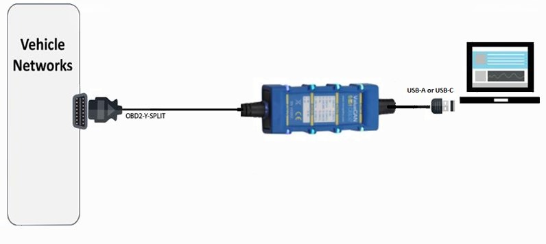
Figure 6. ValueCAN4-X connected to OBD-II (ValueCAN4-4-OBD or VaueCAN4-EL-ODB-II)
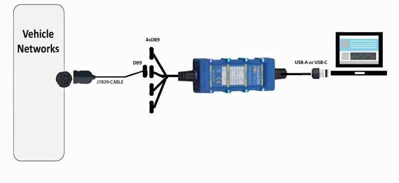
Figure 7: Connector Diagram with ValueCAN4-4XDB9 Deutsch 9-Pin (J1939-RP1210) Cable (DB-9F to Deutsch 9-Pin) Part # J1939-CABLE
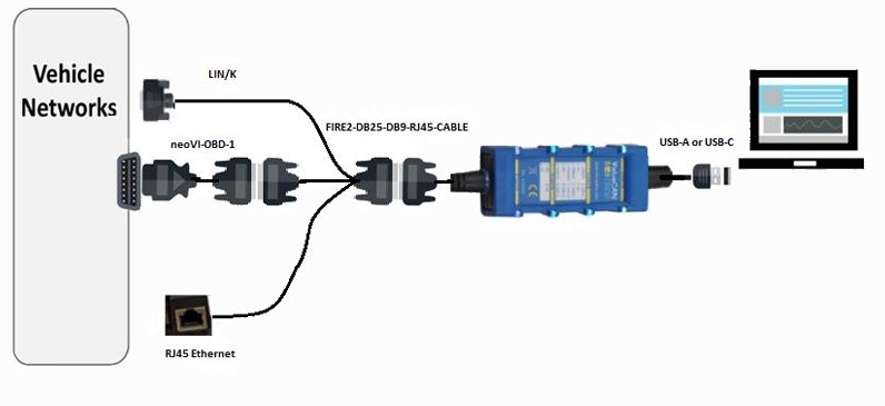
Figure 8: Connector Diagram with ValueCAN4-X (ValueCAN4-4-DB26 or ValueCAN4-2EL-DB26) with Fire2-DB25-DB9-RJ45 Cable and neoVI-OBD-1 Cable
4.2. Power and Vehicle Network Connections
The ValueCAN 4-4 is powered exclusively from the 5V USB connection.
The ValueCAN 4-2EL requires external power.
Network connections to vehicles or test benches are made through the OBD2-II, DB26HD, DB9 or DB25 connections. CAN termination is integrated into the ValueCAN4-X and can be enabled from the VSpy Hardware Setup/neoVI Explorer software interface.
Caution
Caution: The ValueCAN4-X can only be powered via the USB cable.
Caution
Caution: CoreMini scripts run when the device is powered and not connected to a PC’s USB port (that is, enumerated). Therefore to run a script stand alone, it is recommended to use a power-only USB cable to prevent enumeration. Using a charger or power pack to power the ValueCAN4-X will also work
4.3. PC Connection
Connect the USB Type A/USB C to USB port on the PC. A powered USB hub can be used to connect the ValueCAN4-X, but performance varies due to the quality of the hub and its ability to provide power. We recommend a direct connection to a native USB port unless unavoidable. If a USB hub must be used, make sure to use a high-power USB hub and test the hub with the ValueCAN4-X before use.