
|
LEDs |
As the device layout shows, the neoVI PLASMA has many LEDs.
There are 2 top facing LEDs for the SD cards and 10 front facing LEDs (Figure 1) that indicate device conditions as described in Table 1. Table 1: neoVI PLASMA LED Pattern Defaults
Table 2: Vehicle Spy LED Mapping for neoVI PLASMA
Last Update:
Saturday, April 20, 2013
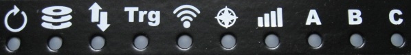
Figure 1: These LEDs indicate the status of some neoVI PLASMA features.
LED
Pattern
Description
SD Card LEDs
(on top side)Off
SD card removed.
Solid Green
SD card inserted.
Solid Red
SD card is logging data.
Blink Red
Core firmware is being updated.
All LEDs
TogetherSolid Yellow
neoVI PLASMA is going to sleep.
Solid Red
VNET firmware is being updated.
OR
Internal communication fault between HID and VNET.
 LED #1
(red)
+
 LED #2
(green)
TogetherBlink Green alone
Powered, but not doing anything.
Blink Red alone CoreMini is running.
Alternate Red/Green
Online with Vehicle Spy.
Blink Red
Green Blinks SlowlyLogging pre-trigger data.
Blink Red
Green Blinks QuicklyLogging post-trigger data.
Blink Red 1x
Blink Green 3xVNET in bootloader mode.
Both Solid Yellow
Waiting to sleep after PC USB is disconnected.
 LED #3
Blink White
Data uploading to Wireless NeoVI server before going to sleep.
 LED #4
Off
GPS signal not locked in.
Solid Blue
GPS signal locked in.
 LED #5
Off
Modem's PWRMON signal indicates modem is off.
Solid Green
Modem's PWRMON signal indicates modem is on.
 LED #6
Solid Green
Wireless NeoVI license is valid and not expired.
Solid Blue
Wireless NeoVI license is valid, but expired.
Solid Red
Wireless NeoVI license is invalid.
 LED #7
 LED #8
 Unused
 LED #9
Off
Modem driver is idle or off.
Green
Modem driver onoff signal is being pulsed to turn modem on.
Yellow
Modem driver is waiting for PWRMON or CTS to reach correct state.
Purple
Modem driver 10 s delay. (required by modem's software user manual)
Blue
Modem driver onoff signal is being pulsed to turn modem off or is sending AT commands for sleep.
 LED #10
Solid Yellow
Stays on 5 s every time Linux sends an internal communication update to HID.
LED Control, Colors, and Mapping (for advanced users)
All front facing LEDs can be controlled using a Vehicle Spy CoreMini script.
All of the LEDs are multicolor, including those used for backlighting the buttons.
One way to control a neoVI PLASMA LED in Vehicle Spy is to follow these steps:
* LED colors can be any of these values:
Builder
NameVSpy
#neoVI PLASMA
LED
Builder
NameVSpy
#neoVI PLASMA
LED
1
0
Top row LED #1
n/a
18
Bottom button 5
2
1
Top row LED #2
n/a
19
Bottom button 4
3
2
Top row LED #3
n/a
20
Bottom button 3
4
3
Top row LED #4
n/a
21
Bottom button 2
5
4
Top row LED #5
n/a
22
Bottom button 1
6
5
Top row LED #6
n/a
23
Left Android Back button
7
6
Top row LED #7
n/a
24
Left Android Menu button
8
7
Top row LED #8
n/a
25
Left Android Home button
9
8
Top row LED #9
n/a
26
Right keypad UP button
10
9
Top row LED #10
n/a
27
Right keypad RIGHT button
n/a
10
Right Android Back button
n/a
28
Right keypad DOWN button
n/a
11
Right Android Menu button
n/a
29
Right keypad LEFT button
n/a
12
Right Android Home button
n/a
30
Right keypad CENTER button
n/a
13
Bottom button 0
n/a
31
Left keypad UP button
n/a
14
Bottom button 9
n/a
32
Left keypad RIGHT button
n/a
15
Bottom button 8
n/a
33
Left keypad DOWN button
n/a
16
Bottom button 7
n/a
34
Left keypad LEFT button
n/a
17
Bottom button 6
n/a
35
Left keypad CENTER button
 neoVI PLASMA Documentation - (C) Copyright 2019 Intrepid Control Systems, Inc.