To indicate how the value is encoded in the Throttle Position signal, an equation needs to be entered for it.
Throttle position can have many possible values. It is variable and therefore analog rather than digital. The signal type can be selected from the dropdown list at the top of the Edit Signal Dialog. Select Analog from the list for this example.
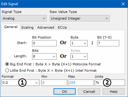
Next, tell Vehicle Spy which bits and bytes in the message to decode. Click on the Start Bit field and make sure the Bit Position is set to 0. The Length needs to be set to 8 bits. This setup will set the first byte of the Engine Parameters message as the raw value of the Throttle Position signal. Leave the endianness set to the default of Big End First.
The Format option (Figure 1: )
tells Vehicle Spy how to show the data returned. Select 0.0 from the list.
With this setting the signal will be displayed with one place after the decimal point. The minimum
of 0 and the maximum of 255 will automatically populate.
Type % in the Units field (Figure 1: ).
This will cause the Throttle Position values to be displayed with % as its engineering units.


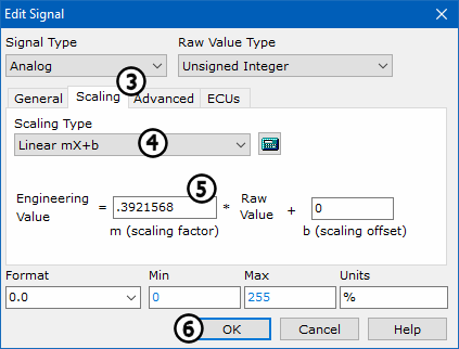
Select the Scaling tab (Figure 1: ). This tab
is where the equation to convert raw data into real world engineering values is done. Select
Linear mX+b in the Scaling Type field
(Figure 1:
 ). Enter a linear scaling factor of
0.3921568 in the Engineering Value field
(Figure 1:
 ). This value will scale an 8 bit value to a percent.
(0.3921568 = 100 % / 255 bits).
By default the Raw Value Type is set to Unsigned Integer.
Press OK to complete equation  .
.
*Note: If we were decoding digital signals, the procedure would be very similar. Simply select Digital for Signal Type and then enter the bit position for the signal.