3. A Tour of RAD-Epsilon Hardware
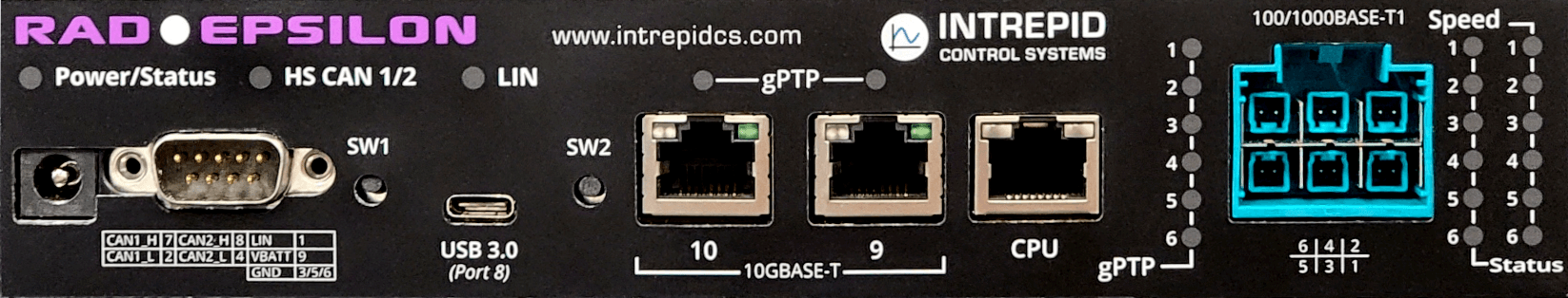
Before learning how to configure and set up the device, let’s examine the device from all sides to understand all of its interfaces and status indicators.
3.1. LED Indicators
3.1.1. Power/Status
Color |
State |
|---|---|
Orange |
Device is Powered |
White |
Connected with a USB host |
Blue/Green Flash |
Online with VSPY |
Magenta |
Embedded Script Running |
3.1.2. HS CAN 1/2
Color |
Status |
Green |
Message Transmitted |
Blue |
Receive Received |
Cyan |
Messages Transmitted and Received |
Red (flashing) |
Errors at slower message rate |
Red/Green (flashing) |
Errors at a higher message rate |
3.1.3. LIN
Color |
State |
|---|---|
TODO |
TODO |
3.1.4. Ports 1-6, (and 9/10 on Epsilon-T)
Green LED (Link Speed) |
1x Flash |
10 Mbps |
2x Flash |
100 Mbps |
|
3x Flash |
1000 Mbps |
|
Amber LED (Link Status) |
Inactive |
Link Inactive |
Solid |
Link Active |
|
Flashing |
RX/TX Activity |
|
Blue LED (gPTP Config) |
Solid |
gPTP Master |
Flashing |
gPTP Slave |
note
SW1 and SW2 are mechanical buttons intended for future use. They currently have no functionality aside from playing a tone from a sound generator contained in the design
3.2. Front Panel Connector Interfaces
3.2.1. Barrel Jack
RAD Epsilon can be powered by the 2.1 mm barrel jack on the left of the front panel. See this section for the power requirements.
3.2.2. DB9 Pinout:
The DB9 is both a power connector as well as contains the CAN FD and LIN networks.
Pin |
Signal |
Pin |
Signal |
|
1 |
LIN |
6 |
GND |
|
2 |
CAN 1 L |
7 |
CAN 1 H |
|
3 |
GND |
8 |
CAN 2 H |
|
4 |
CAN 2 L |
9 |
VBATT |
|
5 |
GND |
|||
3.2.3. USB C :
This connection serves 2 purposes
GIGE / USB Bridge (Port 8 of the 88Q6113)
Data Connection for VSPY 3 and configuration using neoVI Explorer
3.2.4. Ports 9/10: 10GBASE-T Ports:
The RAD Epsilon uses a standard RJ-45 connector for 10GBASE-T ports.
10GBASE-T Ports

The standard RJ-45 jacks on RAD Epsilon have a pair of integrated LEDs that provide information about the RAD-Epsilon’s conventional 10 Gigabit Ethernet connections.
Green LED (Link Speed) |
Inactive |
Link Inactive |
1x Flash |
10 Mbps |
|
2x Flash |
100 Mbps |
|
3x Flash |
1000 Mbps |
|
4x Flash |
10 Gbps |
|
Amber LED (Link Status) |
Inactive |
Link Inactive |
Solid |
Link Active |
|
Flashing |
RX/TX Activity |
3.2.5. CPU:
This port is not connected to the 88Q6113, but a peripheral for the optional use of an NVIDIA Jetson.
note
For a map of switch ports to physical connectors reference the Device Overview
3.2.6. 100/1000BASE-T1 Ports
The 100/1000BASE-T1 ports on RAD Epsilon use MATEnet Connectors located on the right side of the front panel. Port assignments are shown below
RAD Epsilon Cavity Assignments
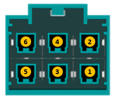
The pin assignments in each connector cavity can be found in the table below (looking into the connector )
Left Pin |
Right Pin |
|---|---|
1000BASE-T1_N |
1000BASE-T1_P |
3.3. Rear Panel
3.3.1. NVIDIA Jetson Nano Peripherals
The following interfaces are all peripherals of the optional NVIDIA Jetson Nano.
HDMI Port
Display Port
2x USB Host Ports
SD Card slot
note
The Video SerDes Connectors on the rear panel of RAD Epsilon are intended for future use and have no functionality at this time