5. The neoVI Explorer Configuration Utility
5.1. Starting and Using neoVI Explorer
This section will describe general features and the basics of using neoVI Explorer. It is the utility is used to connect to, manage and configure all of Intrepid Control Systems hardware. It is an integral part of Vehicle Spy, but for those not using Vehicle Spy software, it is also available as a stand alone application in the free ICS Hardware Installation kit
5.1.1. Starting neoVI Explorer from within Vehicle Spy
There are several ways to open neoVI Explorer from within VSpy. These are probably the two easiest, since they are accessible at all times:
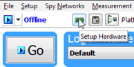
Menu Item: Click the Setup menu and then select Hardware.
Hardware Setup Button: Click the button located in the main Vehicle Spy toolbar just under its menu (Figure below).
Note
neoVI Explorer cannot be launched when Vehicle Spy is online (even if in simulation mode). Attempting to do so, VSpy will display a prompt to either go offline and launch neoVI Explorer, or remain online and return to Vehicle Spy.
5.1.2. Starting neoVI Explorer as a Standalone Program
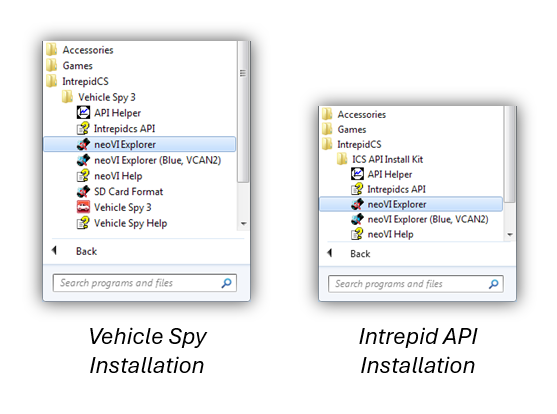
neoVI Explorer can be opened as as standalone program. The location of the shortcut to launch neoVI Explorer differs slightly between a Vehicle Spy installation and the ICS Hardware Installation kit as shown in the following screen captures.
5.2. Interfacing with a device
5.2.1. Connecting to a device
When neoVI Explorer loads, it will start up with the first hardware device it can find selected in the menu pane on the left. Any connected devices should be listed here, along with its serial number. If a particular device is connected, but not seen among a list of other Intrepid devices, be sure to scroll down to look for it. If it is still not visible, this means its drivers have not been installed correctly, it is not powered properly, or there is a problem with the connection to the host computer.
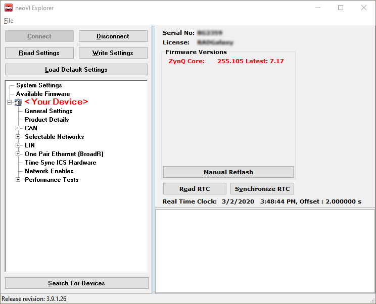
To manage a device, click on its entry in the navigation pane (if it is not already highlighted) and then press the Connect button. After successfully connecting to the device, a “thumbs up” icon will be displayed next to the device’s name, and checkmarks will appear next to currently-enabled networks in the explorer area on the left. A message in the message box on the right will also read “<Your Device and Serial Number> settings have been read”. This indicates that neoVI Explorer has loaded the current settings from the unit.
The screen as a whole should appear similar to the screen shown below (but note that the device and version number shown below may be different).
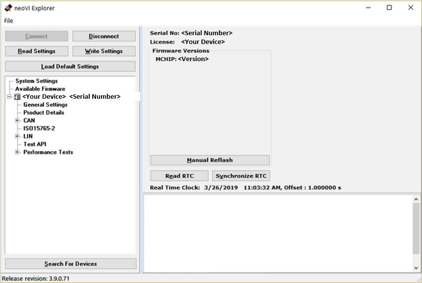
Note that this screen varies in content between Intrepid devices.
Searching for Devices
After attaching new hardware to a PC and starting neoVI Explorer, press the Search For Devices button at the bottom left of the dialog box to prompt the program to scan for new hardware to be managed.
Note
It is possible to click on various parameter groups at any time, but they will not show valid data until connected to the device. Remember also to connect to the device before making changes; Any changes made in neoVI Explorer with no device connected will be overwritten by a devices settings when it is connected.
5.2.2. Device Configuration
Writing and Reloading Settings
To avoid potential problems, neoVI Explorer will not save any changes to device parameters until instructed it to do so. This is done by pressing the Write Settings button, which will update the parameters within the firmware in the device. If unwanted changes were made, pressing the Read Settings button will reload the settings stored in the device, wiping out any modifications made in neoVI Explorer that had not yet been saved.
Reloading Device Defaults
To return all settings to factory defaults, press the Load Default Settings button. Note that pressing this button actually writes the defaults to the device first, and then reloads them automatically, so it is not necessary to also press Write Settings. The message area will display that defaults have been sent to the device and then read from it.
Disconnecting from the device
Press the Disconnect button to tell neoVI Explorer disconnect the device. This step is actually optional, because neoVI Explorer will disconnect from any connected devices when the program is closed.
Exiting neoVI Explorer
Like any Windows program, neoVI Explorer can be closed by clicking the “X” in the top right corner, or pressing the Alt+F4 key combination.
5.3. System Settings and Firmware Updates
The top two entries in the explorer window on the left side of neoVI Explorer contain system- wide settings that apply to all hardware devices, and information related to firmware updates.
5.3.1. System Settings
In the top branch of the tree in the left pane of neoVI Explorer there are several settings that can be enabled or disabled:
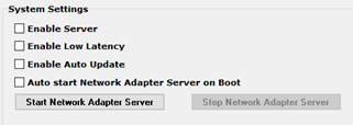
Enable Server: Turns on the neoVI Server feature, a background program that allows the hardware to be used by multiple applications at the same time.
Enable Low Latency: This is an advanced setting for applications where fast response is needed after transmission.
Enable Auto Update: When enabled, both neoVI Explorer and Vehicle Spy will automatically update firmware. If this box is not checked, firmware must be updated manually. (See below for details.)
Network Adapter Server: This is a feature that is used with Intrepid products having Ethernet ports. (It may not apply to your device.) With This feature enabled, the Ethernet ports on Intrepid hardware will enumerate as network interfaces in the operating system of the host computer. This server can be started and stopped in this window. There is also a checkbox to configure the server to start after booting of the computer.
5.3.2. Available Firmware
This is an informational page that shows which firmware versions are available in this version of neoVI Explorer for various Intrepid products. Note that some devices have multiple firmware programs that control different aspects of their operation;
5.3.3. Automatic and Manual Firmware Updates
Warning
While a device may appear to operate with incompatible firmware, proper and reliable operation cannot be guaranteed unless the version of firmware matches what is listed in Vehicle Spy
Firmware is essentially software that runs inside hardware and is required to enable the many capabilities of a device. New versions of firmware are created regularly by Intrepid’s engineers to implement new features and correct problems that have been identified.
Enable Auto Update is on by default and is recommended for most users. Each time a device connects neoVI Explorer or Vehicle Spy, the firmware will be checked, and if a newer version is available, the device will immediately be updated. If automatic updates is not enabled, it can be updated manually as needed. When new firmware is available, a red notification will be displayed on the initial connection screen, as shown below. Simply press the Manual Reflash button to update the firmware.
Note that this screen varies in content between Intrepid devices.
5.3.4. The Firmware Update Process
During the firmware update process, the device will be placed into bootloader mode, indicated by all LEDs on the top label flashing synchronously. Normal LED flash patterns will resume when the update is complete and the device reboots. The progress of the firmware update operation is displayed in a dialog box as shown below. A message box on the right side of neoVI Explorer will also be displayed as the firmware program is sent to the device. When the process is complete the dialog box will disappear and another message will appear in neoVI Explorer to confirm that the update has finished. If any error messages are displayed or any other problems experienced updating the device’s firmware, please contact Customer Support for assistance.
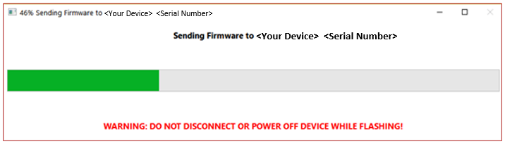
Warning
Please take heed of the warning on the firmware update dialog box: leave the device connected and powered on for the entire firmware update process to avoid possible problems with the device.
5.4. General Settings and Product Details
These two areas of the device’s parameter setup provide information about the device and can be used to perform a few basic maintenance tasks.
5.4.1. General Settings
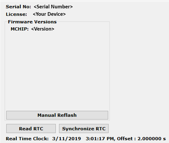
After connecting to the device, basic information about it will be displayed in the right-hand pane of the window:
The device’s serial number.
The firmware versions currently in the device, and an indication if new firmware is available.
A message showing that the hardware license for the device was recognized.
A current readout of the device’s real-time clock.
This information can be displayed again at any time by clicking the device’s name in the explorer navigation window, or the General Settings entry immediately below it.
The version(s) of the firmware for the device will be shown in black if it matches the firmware version within neoVI Explorer. If not, the current version and the newest available version will be shown in red to highlight that an update is available. (See the previous section for more about the update process.)
There are three buttons on this screen.
Manual Reflash (described in the previous section)
Read RTC button will reload the device’s internal time clock
Synchronize RTC will set the device’s clock to the same value as that of the PC.
5.4.2. Product Details
This is an informational area that provides technical data on the devices’s hardware and internal setup. This is generally only needed this if requested by Intrepid in order to facilitate support or troubleshooting. The Copy To Clipboard button can be used to copy all of the information to the Windows Clipboard to be pasted into an email or file.
5.5. CAN Network Settings
5.5.1. CAN Networks
This area of neoVI Explorer is used to enable, disable and configure the High Speed CAN channels. Each channel has an entry under the “CAN” group (which cannot be clicked itself). The current status of each channel is shown next to its name; a green checkmark indicates that the channel is enabled, while a red X means it is disabled. The figure below shows an example of the CAN channels area, with HS CAN enabled and HS CAN2 disabled.

All of the CAN channels have the same parameters, which can be configured using the controls in the right-hand pane; the default settings are shown below.
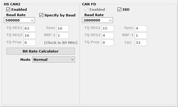
Enabled: Place a checkmark in this box to enable the channel, or clear the checkmark to disable it. When disabled, all of the other parameter controls are disabled (grayed out).
Specify by Baud: This is a master control that determines whether the operation of the channel is controlled by a numeric baud rate, or is calculated from lower-level timing parameters. When checked, the Baud Rate and CAN FD Baud Rate drop-down boxes are enabled and the various TQ, Sync and BRP-1 entries are disabled. When unchecked, this is reversed. Specifying by baud rate is the default, and is recommended except for advanced users with special requirements.
Baud Rate: When Specify by Baud is selected, choose a baud rate for the channel from the drop-down box below. The default value is 500000.
CAN Timing Settings: When Specify by Baud is deselected, the operation of the CAN channel is based on these five settings: TQ SEG1, TQ SEG2, TQ Prop, Sync, BRP-1. These settings are for advanced users and normally should be left at their default values.
CAN FD Baud Rate: When Specify by Baud is selected, choose a baud rate for the data phase of CAN FD messages. The default value is 2000000.
CAN FD Timing Settings: When Specify by Baud is deselected, use these settings (TQ SEG1, TQ SEG2, TQ Prop, Sync, BRP-1) for the data phase of CAN FD messages. These parameters are for advanced users and normally should be left at their default values.
Mode: The operating mode of the channel; choose from one of these four options:
Normal: Normal operation (default).
Disable: Channel is disabled.
Listen Only: This channel only receives messages, with no transmissions, and also no error frames generated nor acknowledgments sent.
Bit Rate Calculator: Press this button to launch the Intrepid Bit Timing Calculator.
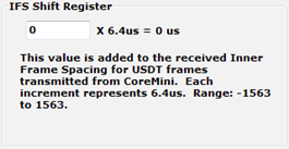
5.5.2. ISO15765-2:
This page contains one setting: IFS Shift Register (shown below). Changing this from its default value of 0 causes time to be added to the Inner Frame Spacing of USDT frames transmitted by CoreMini scripts running in the FIRE 2. The number entered is multiplied by 6.4 µs to determine the time offset. The allowed range is -1563 to 1563.
5.6. LIN Network Settings
This section the device’s explorer tree allows enabling, disabling and configuring its LIN channels. Each channel has an entry under the “LIN” group (seen below). As with the CAN channels, a green checkmark indicates that a particular channel is enabled, while a red X means it is disabled.

All of these channels have the same parameters, which can be seen below. In this image we have selected the Advanced Options checkbox to display its options (described below).
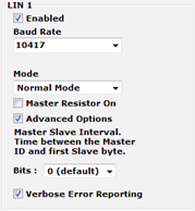
Enabled: Place a checkmark in this box to enable the channel, or clear the checkmark to disable it. When disabled, all of the other parameter controls are disabled (grayed out).
Baud Rate: Select a baud rate for the channel; the default is 10417.
Mode: This option is currently not used and should be left at the default of “Normal Mode”.
Master Resistor On: Enable this option for the device to act as the master on the specified LIN bus.
Advanced Options: Click this checkbox to reveal two additional options:
Master Slave Interval: The time between the master ID and the first slave byte, in bits (default 0).
Verbose Error Reporting: When checked, break errors and other error messages from the LIN driver are displayed.
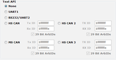
5.7. Text API
These parameters control the operation of the text API that can be used to operate the neoVI FIRE 2 using third party software. Please contact Intrepid Customer Support if any assistance using the API is required.
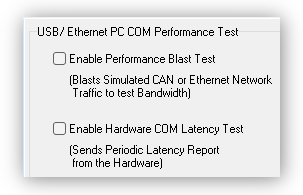
5.8. Performance Tests
The following are tests which can be used to characterize the bandwidth and latency between ICS hardware and its host computer. If problem is encountered with either of these, our Customer Support would be happy to help resolve it. Reference the end of this document for contact information.
5.9. Basic Switch Configuration
5.9.1. Switch Port/PHY Configuration
The following interface is used to configure the PHY of each port of the 88Q6113.
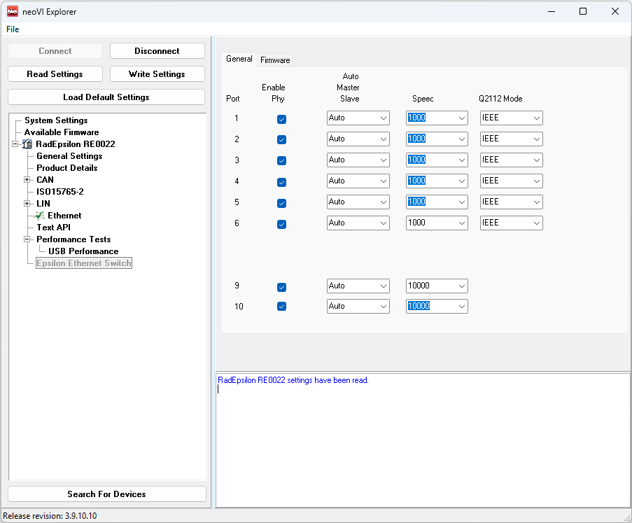
Enable PHY |
Each PHY can be independently enabled/disabled |
Auto/Master/Slave |
Master/Slave setting for each PHY |
Speed |
100/1000 Mbps for ports 1-6 |
100/1000/10000 Mbps for ports 9/10 |
|
Q2112 Mode |
Legacy: Compatible with rev A0 of the Marvell 88Q2112 |
IEEE: Meets IEEE interoperability requirements |
5.9.2. Switch Firmware and MAC Spoofing
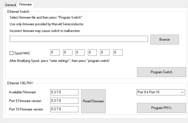
88Q6113 Firmware Update
Provided your company has an NDA with Marvell Semiconductor, you may receive updates to the firmware of the 88Q6113 which executes the AVB/TSN Protocols. This interface allows selecting the binary image of the Marvell firmware and it is programmed when the “Program Switch” button is pressed.
Always verify the proper firmware image is being used
Programming the switch firmware with an incorrect image can make the switch malfunction or become inoperable. Use only firmware images obtained directly from Marvell and insure it is the proper version for the 88Q6113
MAC Spoofing
Your device was programmed with a unique MAC address when it was manufactured. However, this can be changed if you would like to change this address for testing purposes. In order to do this, the firmware must also be updated, therefore a binary image of this firmware is required.
Step 1: Select the binary file containing the Marvell firmware. Use only files provided by Marvell Semiconductor or the switch may not function properly.
Step 2: Enter the desired MAC address here with the box checked and press “Write Settings”. This stores the MAC address to be programmed along with the firmware.
Step 3: Press “Program Switch” to update the firmware and change the MAC address (if spoofing is enabled).
10GBASE-T PHY Firmware Update
The bottom section of this configuration screen can update the firmware of the 10G PHYs on Ports 9 and 10. Pressing the “Read FW” button will display the PHY firmware compared to the firmware available in the build of Vehicle Spy Software currently installed. This is not common, but if there is newer firmware available, it can be programmed by pressing the “Program PHYs” button. This operation can take several minutes to complete.