7. Advanced Features
7.1. Device Register Access
7.1.1. MDIO Protocol
Most Ethernet PHYs and switches communicate using MDIO protocol (Management Data Input/Output). Using this protocol, internal registers can be accessed to configure the device as well as read information from the device such as its current configuration and status information.
Each MDIO frame is 32 bits:
2 start bits
2 bit operation code
5 bit phy address
5 bit register address
2 bit turn around delay
16 bits of data.
As Ethernet devices has evolved over the years, so has the protocol used to communicate with them. Devices in Intrepid products use either Clause 22 or Clause 45, which will be explained in the following sections.
Clause 22
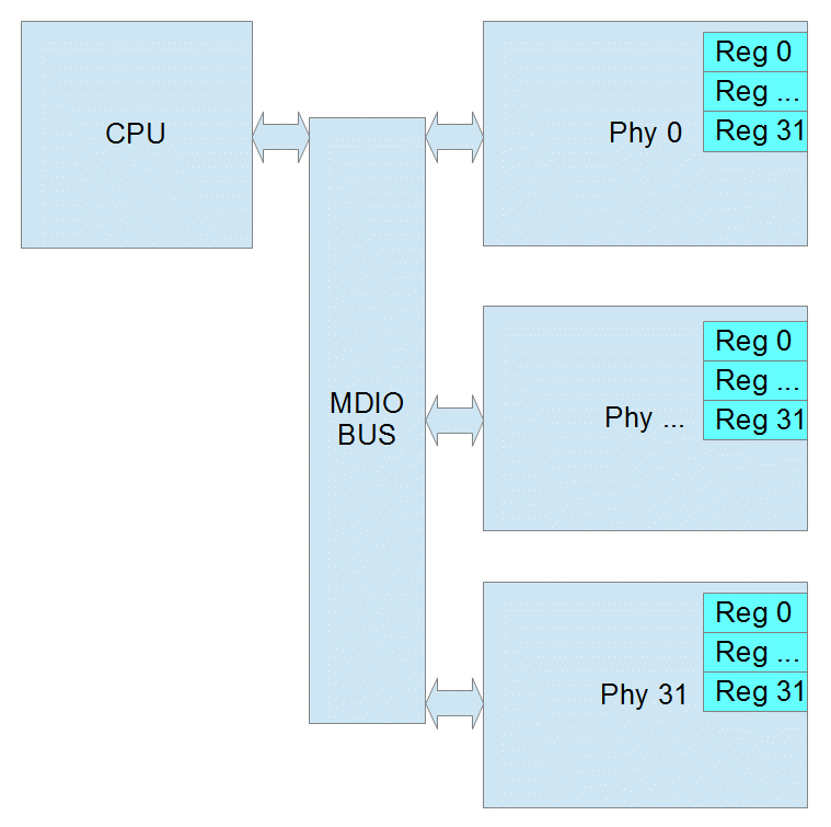
The initial protocol, IEEE 802.3 Clause 22, was designed to read or write 32 registers within 32 devices. Each read/write is done in one operation.
Phy Address 5 bits (0 – 31 decimal)
Register address 5 bits (0 – 31 decimal) or (0 – 1F hex)
Data 16 bits

Page Register
Some Ethernet Phy manufacturers added a page register to allow for more registers in Clause 22. The page can be 0 – 255 decimal. If the Phy does not support pages, then page will be ignored. When using pages, reads and writes can no longer be performed in one operation. Instead you must write to the page register and then before any other process changes the page, you can read or write the destination register. If another process were to change the page register before you finish, the result will be an read the wrong register or an write to wrong register which may cause the Phy to stop working.
Common Clause 22 Registers
Clasuse 22 Registers |
Bits |
Function/Status |
|
|---|---|---|---|
Control Register (Register 0) |
15 |
reset |
|
14 |
loopback |
||
12 |
auto negotiate |
||
11 |
power down |
||
10 |
isolate |
||
9 |
renegotiate |
||
8 |
duplex |
||
7 |
collision test |
||
6/13 |
speed |
10=1000mbps |
|
01=100mbps |
|||
00=10mbps |
|||
Status Register (Register 1) |
5 |
Auto Negotiation Complete |
|
4 |
Remote Fault |
||
3 |
Auto Negotiation Capability |
||
2 |
Link Status |
||
1 |
Jabber Detect |
||
0 |
Extended Capability |
||
Phy ID Reg 1 (Register 2) |
15:0 |
OUI MSB |
|
PHY ID Reg 2 (Register 1) |
15:10 |
OUI LSB |
|
9:4 |
Model Number |
||
3:0 |
Revision Number |
||
Clause 45
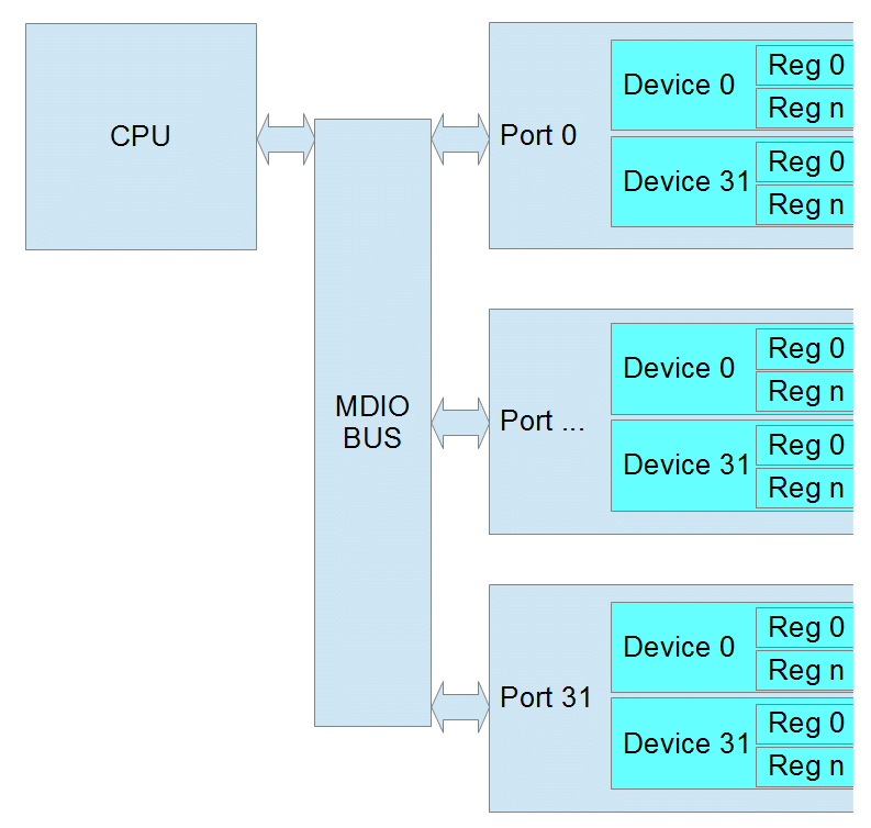
As Ethernet Phys became more complicated and supported different speeds and connections, IEEE 802.3 Clause 45 was added. Because the Register Address is now 16 bits, each read/write takes at 2 operations. The first operation is always writing the Register Address that you want to use in the next operation. The second is the actual read or write. There is also a special read that increments the address after each read which allows you to write a starting address and then read a whole block of registers.
Port 5 bits (this is equivalent to the Phy Address)
Device 5 bits (this is similar to the page)
Register address 16 bits (this allows 65536 registers in each device)
Data 16 bits

Common Clause 45 Registers
PMA/PMD Registers
Device |
Register |
Bits |
Function/Status |
||
Control Register |
1 |
0 |
15 |
reset |
|
11 |
power down |
||||
6/13 |
speed (10-1000mbps) |
11=Speed set by bits 5:2 |
|||
10=1000mbps |
|||||
01=100mbps |
|||||
00=10mbps |
|||||
5:2 |
speed (2.5-10 Gbps) |
0111=5 Gbps |
|||
0110=2.5 Gbps |
|||||
0000=10 Gbps |
|||||
Device ID Reg 1 |
1 |
2 |
15:0 |
Auto Negotiation Complete |
|
Device ID Reg 2 |
1 |
3 |
15:10 |
OUI LSB |
|
9:4 |
Model Number |
||||
3:0 |
Revision Number |
||||
PCS Registers
Device |
Register |
Bits |
Function/Status |
||
|---|---|---|---|---|---|
Control Register |
3 |
0 |
15 |
reset |
|
14 |
loopback |
||||
11 |
power down |
||||
6/13 |
speed |
10=1000mbps |
|||
01=100mbps |
|||||
00=10mbps |
|||||
Device ID Reg 1 |
3 |
2 |
15:0 |
Auto Negotiation Complete |
|
Device ID Reg 2 |
3 |
3 |
15:10 |
OUI LSB |
|
9:4 |
Model Number |
||||
3:0 |
Revision Number |
||||
7.1.2. Using MDIO with Intrepid Products
Now that the two relevant variants of the MDIO protocol are understood, reading and writing registers requires the following information.
MDIO protocols supported by each port of your hardware are listed in the table below.
MDIO Addresses of the device: In many cases, there can be multiple MDIO busses in a system. Therefore, in addition to the address of the device, it is necessary to know which MDIO bus is used to communicate with it. The device addresses and their corresponding MDIO Bus Index can be found in the table below.
Register Information: Most devices support the common register addresses listed earlier in this section. However, there are many other manufacturer-specific registers that can be useful. This information is usually found in the manufacturer’s data sheet. It is often confidential and requirements and NDA (Non Disclosure Agreement) with the manufacturer.
MDIO Address Table
RAD-Epsilon MDIO Addresses
The MDIO addressing for the switch and Ethernet ports of of the RAD-Epsilon are as follows.
Device |
Port |
MDIO Bus Index |
PHY Address |
Protocol |
RAD-Epsilon Switch |
88Q6113 |
0x0 |
0x16 |
Clause22 |
RAD-Epsilon - PHYs |
1 |
0x0 |
0x01 |
Clause45 |
2 |
0x0 |
0x02 |
||
3 |
0x0 |
0x03 |
||
4 |
0x0 |
0x04 |
||
5 |
0x0 |
0x05 |
||
6 |
0x0 |
0x06 |
||
9 |
0x0 |
0x10 |
||
10 |
0x0 |
0x14 |
7.1.3. Using MDIO in Vehicle Spy 3
Coming Soon!
7.1.4. Using MDIO with Intrepid’s Open Source API
libicsneo is the Intrepid Control Systems cross-platform device communication library.
Installation and usage documentation can be found within each of the respective APIs.
C++ MDIO Example:
The following code block is an example of writing and reading to a register using the C++ API .
// We can transmit messages to write to arbitrary register
std::cout << "\tTransmitting a MDIO request to write register on 88Q2112...\n";
mdio_r = std::make_shared<icsneo::MDIOMessage>();
mdio_r->network = icsneo::Network::NetID::MDIO1;
mdio_r->phyAddress = 0x06u;
mdio_r->devAddress = 0x01u;
mdio_r->regAddress = 0x0902u;
mdio_r->data = {0xA3, 0x02};
mdio_r->direction = icsneo::MDIOMessage::Direction::Write;
mdio_r->clause = icsneo::MDIOMessage::Clause::Clause45;
ret = device->transmit(mdio_r); // This will return false if the device does not support MDIO
std::cout << (ret ? "OK" : "FAIL") << std::endl;

// We can transmit messages to read back to arbitrary register
std::cout << "\tTransmitting a MDIO request to read register on 88Q2112...\n";
mdio_r = std::make_shared<icsneo::MDIOMessage>();
mdio_r->network = icsneo::Network::NetID::MDIO1;
mdio_r->phyAddress = 0x06u;
mdio_r->devAddress = 0x01u;
mdio_r->regAddress = 0x0902u;
mdio_r->direction = icsneo::MDIOMessage::Direction::Read;
mdio_r->clause = icsneo::MDIOMessage::Clause::Clause45;
ret = device->transmit(mdio_r); // This will return false if the device does not support MDIO
std::cout << (ret ? "OK" : "FAIL") << std::endl;
An complete example of how to use MDIO through the C++ API can be found here: MDIO C++ Example
Python MDIO Example:
The following code block is an example of writing and reading to a register using the Python API .
import icsneopy

a = icsneopy.MDIOMessage()
a.network = icsneopy.Network(icsneopy.Network.NetID.MDIO1)
a.phyAddress = 0x00
a.regAddress = 0x02
a.direction = icsneopy.MDIOMessage.Direction.Read
a.clause = icsneopy.MDIOMessage.Clause.Clause22
dev.transmit(a)

b = icsneopy.MDIOMessage()
b.network = icsneopy.Network(icsneopy.Network.NetID.MDIO1)
b.phyAddress = 0x00
b.regAddress = 0x18
b.direction = icsneopy.MDIOMessage.Direction.Write
b.clause = icsneopy.MDIOMessage.Clause.Clause22
dev.transmit(b)
C MDIO Example
Coming Soon!
7.1.5. Vehicle Spy’s PHY Dashboard
PHY Dashboard is a feature of Vehicle Spy 3 allowing simple device register reads and writes using MDIO.
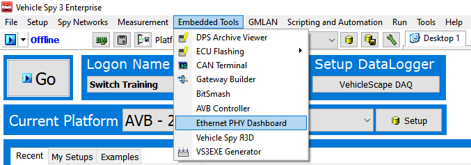
Opening the PHY Dashboard
The PHY Dashboard can be opened from the Embedded Tools menu in Vehicle Spy (shown below)

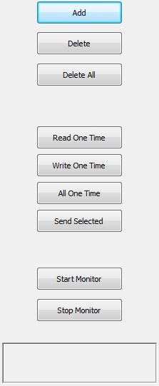
PHY Dashboard Interface
Add – use this button to add MDIO operations. Ctrl-S saves screen contents to VS3 file.
Delete – deletes the currently selected item or item.
Delete All – deletes all operations
Read One Time – performs all reads from the list once. No writes are performed.
Write One Time – performs all writes from the list once. No reads are performed.
All One Time – performs every item in the list once.
Send Selected – performs only the selected item or items once.
Start Monitor – performs all reads once per second.
Stops Monitor – stops the monitor operation.
Note: all values in Hex except Phy Address/Port

PHY Dashboard Examples
Clause 22 Example:

Line 1 writes soft reset to phy address 16, using Clause 22
Line 2 reads Phy ID Reg1 from phy address 16 using Clause 22
Line 3 reads Phy ID Reg2 from phy address 16 using Clause 22
Clause 45 Example:

Line 1 writes soft reset of PCS to Port 16, Device 3 using Clause 45
Line 2 reads PCS ID Reg1 from Port 16, Device 3 using Clause 45
Line 3 reads PCS ID Reg2 from Port 16, Device 3 using Clause 45
MDIO Addresses for your hardware
Reference this MDIO address table for the addresses specific to your hardware.
7.2. Configuring Marvell Switches
The physical ports of the Marvel switch can be configured in neoVI Explorer as detailed in the section titled Basic Switch Configuration.
The functionality of the switch including VLANs, gPTP, Stream Reservation, and TCAM can be configured using the Marvell configuration utility. Given this is software and the device specifications are owned and controlled by Marvell, it must be obtained directly through Marvell’s Extranet or your company’s FAE.