7. Core Feature Operation
Now that we have completed installing and configuring our hardware and software, we are ready to use the neoVI RED 2. As discussed at the start of this guide, you can do a lot with this little box, and in this chapter we show you just some of the many applications of the RED 2.
Each of the sections contains an example application, and where possible, step-by-step instructions are provided for those who wish to duplicate the results on their own device. The goal of this chapter is specifically to assist those who are new to Intrepid hardware and software, and so simplified examples are provided. Advanced users may wish to skim or even skip this chapter. Note that some sections of this chapter will be written in future updates of the manual.
The examples use Intrepid’s Vehicle Spy 3 Professional, the ideal tool for working with your RED 2. Due to the complexity of Vehicle Spy, we only describe the basics necessary for the examples; for full details on this powerful software tool, please see the separate Vehicle Spy documentation.
7.1. Monitoring Conventional Vehicle Networks
The most basic use of the RED 2 is to monitor the activity on conventional vehicle networks such as CAN or LIN. Once the device is connected to the network and correctly configured, this is actually very easy to do, assuming you have the right software. In our example we will show how the neoVI RED 2 can monitor CAN traffic on a bench network using Vehicle Spy 3.
Assuming that your network already has CAN messages being transmitted by other devices, we can monitor that traffic with these simple steps:
1. Launch Vehicle Spy: Start Vehicle Spy by double-clicking its icon or selecting it from the Windows Start Menu.
2. Select neoVI RED 2: On the Logon Screen, select the neoVI RED 2 if it does not already have a checkmark next to it. To do so, right-click the device name and choose Select Hardware (Figure 70)
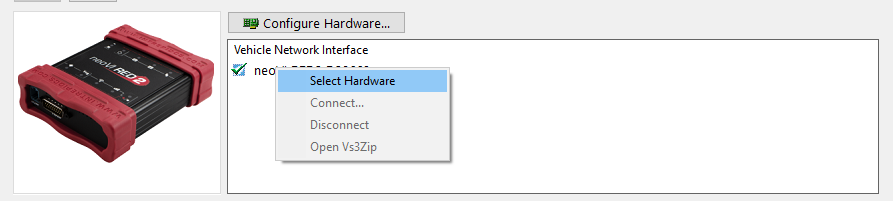
Figure 70: Selecting the neoVI RED 2 from the Logon Screen of Vehicle Spy.
3. Go Online: Press the blue arrow button in the top left corner of Vehicle Spy.
The program will go online and automatically switch to Messages View, showing you the incoming traffic. An example can be found in Figure 71, which shows CAN messages that are being transmitted to the RED 2 by another network interface tool. By default, identical messages will be grouped together; if you prefer to see the messages in chronological order, press the Scroll button located just above the message display.
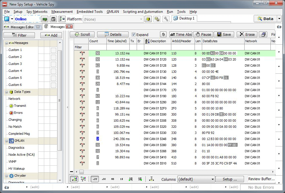
Figure 71: Monitoring Message Traffic in Vehicle Spy Using the neoVI RED 2.
Notice that the CAN messages are shown in their raw form, with arbitration IDs and data bytes. If you have a database matching the message traffic being monitored, you can load it into a platform and Vehicle Spy will decode the messages and show the signals within each. For details on how to accomplish this, please consult the Vehicle Spy documentation.
7.2. Transmitting on Conventional Vehicle Networks
In addition to monitoring network traffic with the neoVI RED 2, we can also easily generate and transmit traffic of our own. We’ll show how this is done by creating and then transmitting a custom CAN message on the DW CAN channel.
First, make sure the neoVI RED 2 is connected to your vehicle network. Then follow these steps to create and transmit a message:
1. Launch Vehicle Spy: Start Vehicle Spy by double-clicking its icon or selecting it from the Windows Start Menu.
2. Select neoVI RED 2: On the Logon Screen, select the neoVI RED 2 if it is not already selected: right-click the device name and choose Select Hardware (see Figure 79).
3. Load Messages Editor: Select Messages Editor from the Spy Networks menu.
4. Select Transmit Messages: Click the Transmit button, found in the blue bar.
5. Create Transmit Message: To the right of the drop-down box that currently says DW CAN”, click the  button.
Vehicle Spy will generate a new DW CAN transmit message called “Tx Message DW CAN 01”, preset with default values. The program window should now appear similar to Figure 72.
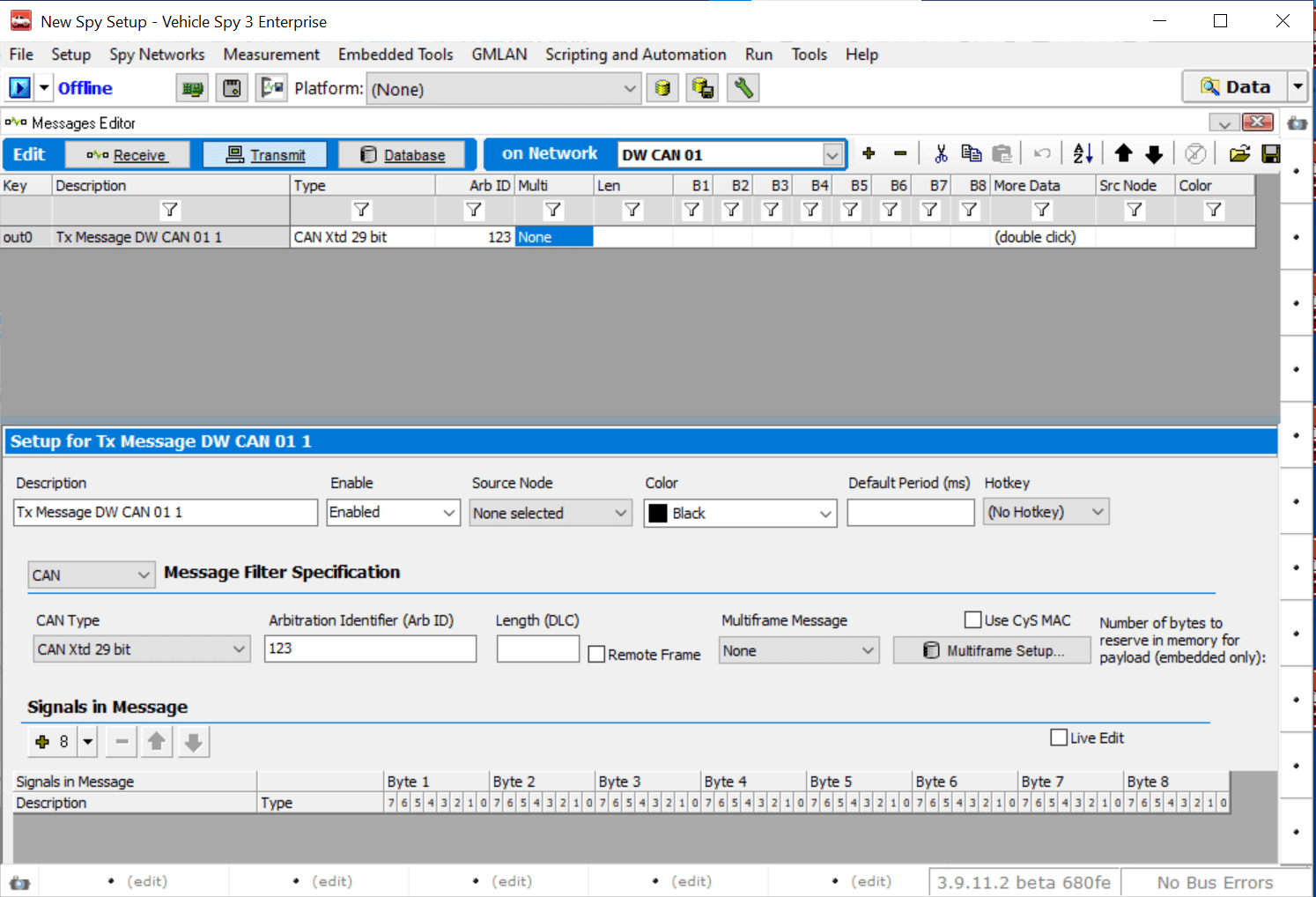
Figure 72: A Default Transmit Message Created in Vehicle Spy.
Next, we will change the default message by assigning an arbitration ID to it, and then adding a signal and renaming it.
6. Set Message to Arbitration ID 123: Under the Arb ID column for the message, enter the value “123”.
7. Add Message Signal: In the middle of the screen, find “Signals in Message”; just below this click the  button. A signal called “Signal 0” is created.
8. Rename Message Signal: Under the Description column, double-click “Signal 0” and change the name to “Engine Speed”.
With these changes, the message should now appear as seen in Figure 73.
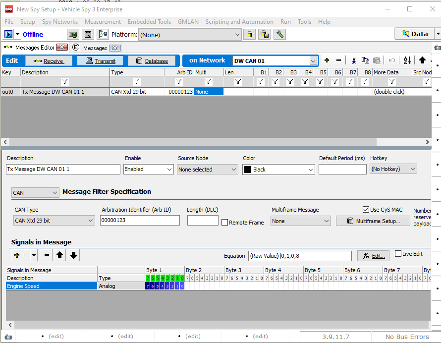
Figure 73: Vehicle Spy Transmit Message with Arb ID and Named Signal
We’ll now use the Tx Panel to specify a simple static value to send in that signal, and then instruct Vehicle Spy to transmit the message periodically.
9. Load Tx Panel: Select Tx Panel from the Spy Networks menu.
10. Select Message: Click on “DW CAN Message 1” under Description on the left side of the screen.
11. Select Transmission Rate: The message by default is set to “Periodic” transmissions, but the rate says “None”. Double-click in this field, scroll down and choose “0.100”.
12. Set Signal Data Value: On the right side of the screen, double-click under Value for the Engine Speed signal, and enter “207”. (You may need to first move the vertical divider bar that separates the two halves of the Tx Panel, by clicking on it and dragging it to the left.)
The Tx Panel in Vehicle Spy should now appear similar to Figure 83. Our custom message is ready to transmit
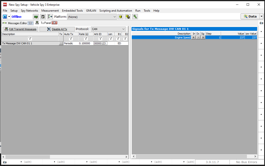
Figure 74: Vehicle Spy Tx Panel with 100 Millisecond Periodic Rate Set and Signal Value Assigned.
Let’s now switch to Messages View and go online to see our message being transmitted on the CAN network.
13. Switch to Messages View: Select Messages from the Spy Networks menu.
14. Go Online: Press the blue arrow button in the top left corner of Vehicle Spy.
You should now see a new “Message DW CAN 1” message show up about every 100 ms (Figure 84). Notice the green dot under the Tx column, which labels this as a transmitted message.
15. Expand Message: Press the + sign to the left of “Message DW CAN 1”.
Vehicle Spy shows you the Engine Speed signal with the value we set in both decimal (237) and hexadecimal (ED).
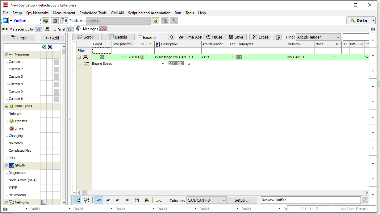
Figure 75: Vehicle Spy Messages View Showing Custom Transmitted Message and Signal.
Naturally, in a real example we would want to create a more realistic depiction of engine speed. This can be done in a variety of ways in Vehicle Spy, such as writing a function block program to describe engine behavior and control message transmission.
7.3. Interfacing to Automotive Ethernet (BroadR-Reach / 100BASE-T1)
The neoVI RED 2 can be used to monitor and transmit on a BroadR-Reach (100BASE-T1) Automotive Ethernet network, with the help of a device that changes the BroadR-Reach PHY into the standard 10/100 Ethernet PHY used by the RED 2. Intrepid sells an inexpensive tool for this exact purpose, called the RAD-Moon media converter.
Figure 76 shows the neoVI RED 2 hookup diagram of Figure 45 modified to illustrate a typical Automotive Ethernet application. The RJ-45 jack on the RED 2 network interface cable is connected to the RAD-Moon’s RJ-45 jack using a standard Ethernet cable. The BroadR-Reach ECU or network is connected to the RAD-Moon’s Mini50 connector on the other side of the converter. Power for the RAD-Moon is provided via the USB host slot on the RED 2, allowing the FIRE 2 to power the RAD-Moon on or off as needed.
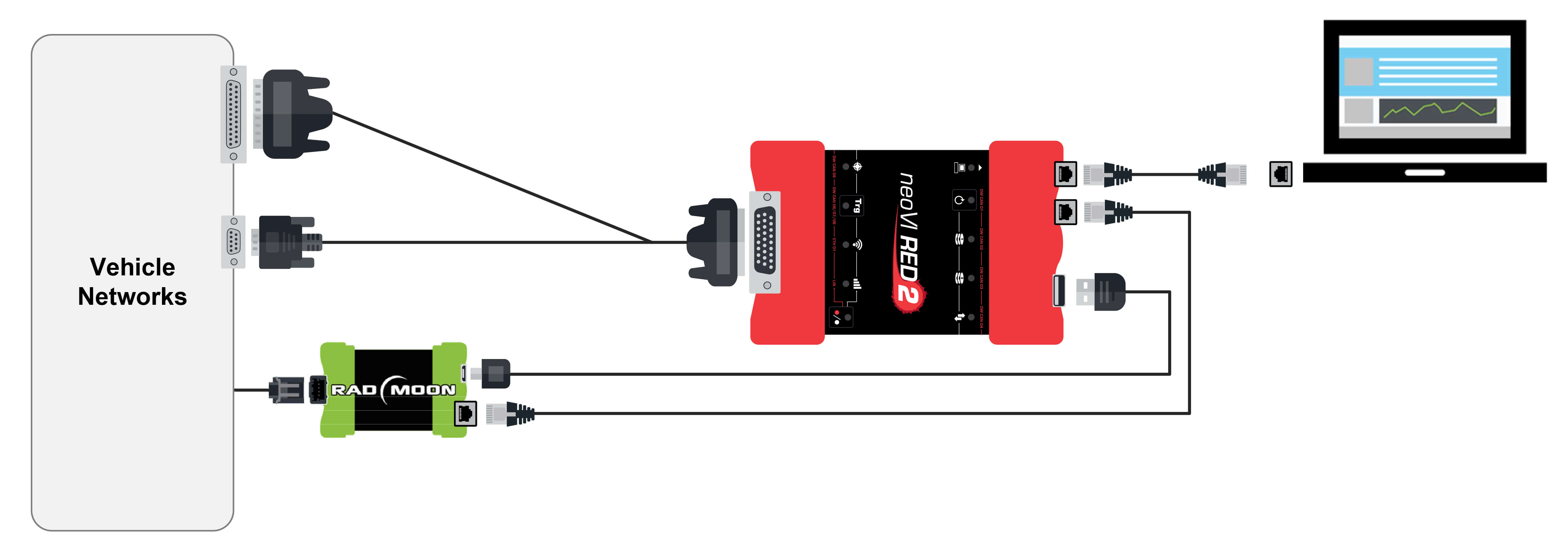
Figure 76: neoVI FIRE 2 Hookup Diagram for Automotive Ethernet Using RAD-Moon Media Converter.
7.4. Using the Ethernet Interface for DoIP and XCP
This section will be detailed in a future version of this manual.
7.5. Using Miscellaneous I/O Channels
This section will be detailed in a future version of this manual.
7.6. Standalone Logging
7.6.1. Build a Standalone Logging Setup:
The Standalone Logging tab (Figures 77 & 78) looks a little overwhelming at first. Taking a closer look, it should be noted that that it is broken down into sections with simple options for how, what, and when to collect data. Details on all the options are in the help topic for the Standalone Logging tab. In this example we will cover the options needed for our original goal of a simple logging setup that uses a pre-post collection.
7.6.2. Set up Message Collection Options:
The Message collection Options (Figure 77:  ) gives options of what to log. The options are to log everything the hardware sees, or just the signals selected on the channels tab. For this example, Entire Bus will be selected to acquire everything the hardware sees.
7.6.3. Set up Collection Start Options:
The Start Options (Figure 77:  ) tells Vehicle Spy when to start logging. In this example a triggered pre-post capture will be created. Select Using Trigger Expression for this example. The next step is to create a trigger condition using the
  button (Figure 77:
  ) and the Expression editor. In this example, the value of a signal collected is examined. This could be any expression that can be built in the expression editor.
Figure 77: Top portion of Standalone Logging Tab gives options for what and when to log.
7.6.4. Set up Collection Configuration:
The next step is to set how many messages to collect. This is done in the Stop section (Figure 77:  ). The default is to finish after collecting 30 seconds of data before and after the trigger event.
7.6.5. Ethernet DAQ / Filter Setup:
The Ehthernet DAQ / Filter Setup is used in specific configurations to collect specific protocols or data types (Figure 78: ). Its use is covered elsewhere in the documentation. For now, move on to the next section.
7.6.6. Set up Reporting Options:
The lower part of this dialog has settings for the hardware. The first section is to set up Status Reporting (Figure 78: ). This gives feed back on what the hardware is doing while it is logging. For this example leave the LEDs option enabled. On a neoVI FIRE, neoVI RED, or neoVI Yellow this will blink the red LED to allow the ability to verify it is running and the green LED will flash as data is being saved to the SD Card. When the capture is triggered, the green LED will flash faster to show this.
Figure 78: Bottom portion of Standalone Logging Tab gives options for the hardware to use
7.6.7. Set up Generate Options:
Options for creating a decoding database and sending the script to the device are given in the Generate section. The option of Generate decoding database (Figure 78: ) and Transfer to SD Card will make a .VSDB file to decode logged data. The option to Transfer to the SD card will save this file on the SD card. When the data is extracted, the .VSDB will also be extracted to the same directory as the data that was collected. This helps keep it all organized.
The last thing to do is click Generate (Figure 78: ). This will build all the function blocks needed to perform the actions configured in the Standalone logging tab. Once everything has been built, the CoreMini Console will load the script.
Note - For further Information about Standalone Logging please refer this video.
7.7. CoreMini Scripting
Your device is capable of running CoreMini scripts independent of a PC, or while connected to a PC and running Vehicle Spy.
Once a script is loaded into the your device, it can run in one of two ways:
- With a script loaded into the device, connect your device to a USB charger, power bank, or other USB power source that does not enumerate your device. Your device will run the script once power is applied and your device is not enumerated or connected to a PC.
- Connect your device to a standard USB port on a computer. When sending the script to the device, use the “Run CoreMini after download” option. This will run the script in the hardware and Vehicle Spy can be used at the same time and perform additional tasks concurrently. TYour device will function in this manner until the script is cleared or disconnected from the USB port.
Please consult the Vehicle Spy documentation for more information on CoreMini scripting