5. Hardware and Software Setup
In this chapter we will explain the steps necessary to set up your neoVI RED 2 to work with a vehicle network. This will include explaining how to install the required software and drivers, connect cables between the RED 2 and the network, and link the unit to a PC.
Note that because vehicle and test bench setups will vary, we can only show a typical case here. You may need to alter these instructions to suit your particular needs.
5.1. Vehicle Spy and Driver Installation and Setup
It is possible to install your hardware and software in either order. However, the neoVI RED 2 requires special drivers to function properly, which are installed automatically by the included software setup programs. If you connect the hardware before the drivers are installed, it will not work correctly. For this reason, we recommend installing the software first.
As mentioned earlier, a fully licensed version of Vehicle Spy is recommended in order to allow you to get the most from your neoVI RED 2. If you purchase Vehicle Spy, you should have received an email with a link to install the software; if not, a driver link should be provided that will give you access to neoVI Explorer to configure your hardware.
Note
A separate driver installer is provided for those who will be interfacing to the neoVI RED 2 using its API, rather than using Vehicle Spy. Please see Section 4.2 for details.
Installing Vehicle Spy (Professional or Trial)
The installation process is very similar for both the full and trial versions, though there may be some slight differences between the figures in this document and what you see on your screen. Vehicle Spy 3 uses an automated installer, which will do most of the work for you. Simply follow the instructions below to set up the program on your computer.
1. Load the Software and Documentation Disc: - Download the software with link, disc or flash drive that came with your neoVI RED 2 into the optical drive of your computer. A few seconds later, the ICS software installation menu should appear on your computer screen, as shown in Figure 20.
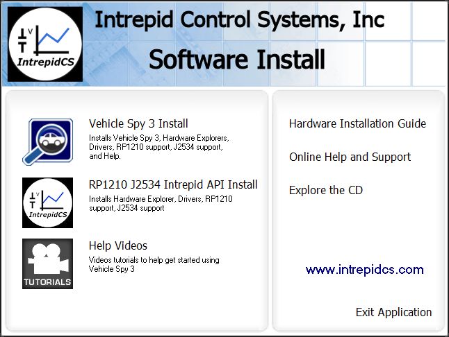
Figure 20: neoVI RED 2 Software Install Dialog Box.
From this menu you can start installing Vehicle Spy 3, install the API support files, and access videos, documentation and online support materials.
2. Start Vehicle Spy 3 Installation: Click Vehicle Spy 3 Install.
3. Select Language: Select your preferred language, and then click OK to proceed. (For the remainder of these directions, we will assume that English has been used.)
The Vehicle Spy 3 setup wizard will now start, displaying a welcome screen as shown in Figure 21 (though the exact version number is likely to differ from the one seen here).
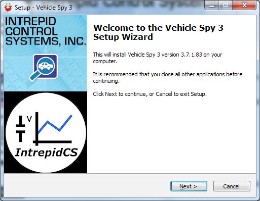
Figure 21: Vehicle Spy 3 Setup Wizard Welcome Screen
4. Start Vehicle Spy 3 Setup Wizard: Click Next > to start the setup wizard.
5. Review and Accept License Agreement: Review the license agreement, and assuming its terms are acceptable, select I accept the agreement, then click Next > (Figure 22).
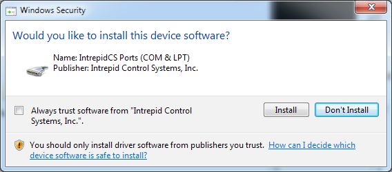
Figure 22: Vehicle Spy 3 License Agreement.
6. Select Installation Type: We are doing a new installation so simply click Next > to continue.
7. Select Destination Location: Choose where you want to install Vehicle Spy 3 (Figure 23). We normally recommend using the default location. Click Next >.
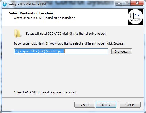
Figure 23: Choosing the Destination Location.
8. Select Data Directory Location: Next, choose where you want Vehicle Spy 3 to store its data files. We recommend sticking with the provided default, C:\IntrepidCS\Vehicle Spy 3 (Figure 24). Click Next > to continue.
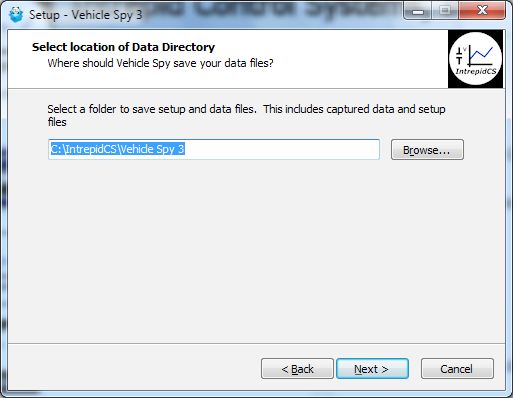
Figure 24: Selecting the Data Directory Location.
9. Select Start Menu Folder: Choose where you want your Windows shortcuts for Vehicle Spy 3 to reside. Again, the defaults are generally fine here, though you can change them if you wish. Click Next > to proceed.
10. Select Additional Tasks: The one option here is to create a desktop icon for Vehicle Spy 3, which is selected by default. Uncheck the box if you do not wish to have this icon created, then click Next >.
You have now provided all of the information the wizard needs to install Vehicle Spy 3. Your selected options will be displayed in a review box, as shown in Figure 25.
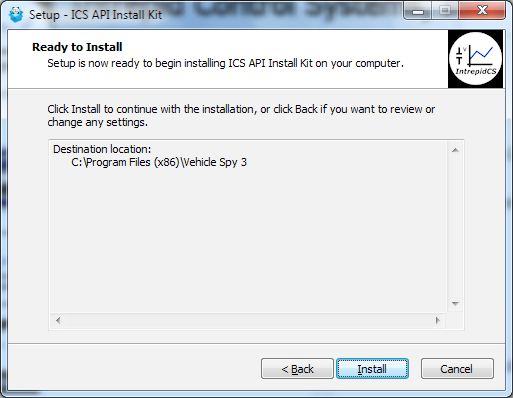
Figure 25: Installation Options Review.
11. Review Installation Options and Begin Installation: Ensure that the options you have chosen are correct, and then click Install.
The wizard will now begin installing Vehicle Spy 3. A window will appear showing you the progress of the installation (Figure 26)
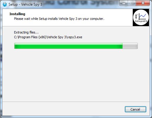
Figure 26: Installing Vehicle Spy 3.
After completing installation of the software itself, the wizard will automatically install various drivers required by Vehicle Spy 3 and the neoVI RED 2. The first install will be guided by the VCP Driver Installer.
12. Install VCP Drivers: Click Next > to begin installing the first set of drivers. This will usually take only a few seconds, and when completed, a message will appear like the one in Figure 27. Click Finish to complete this initial driver installation process.
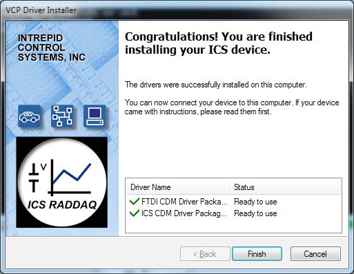
Figure 27: VCP Driver Installation Complete.
Next, support files for Microsoft Visual C++ 2010 and 2005 will be installed, if they are not already on the computer. This happens automatically, and you may briefly see a dialog box like the one in Figure 28. Many systems already have these files, however; if that is the case, a message may appear telling you that they are already present; just hit OK to continue.
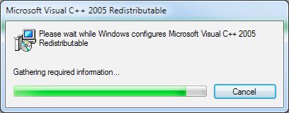
Figure 28: Installing Support Files for Microsoft Visual C++ 2005.
The WinPcap installer will start next. This is a special support program that allows Ethernet traffic on a PC to be captured and displayed by Vehicle Spy 3. You will see a window similar to the one shown in Figure 29.
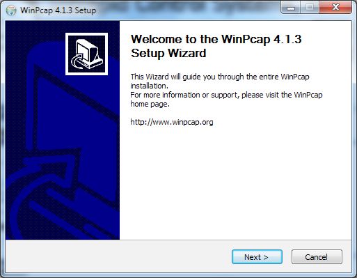
Figure 29: WinPcap setup wizard.
13. Install WinPcap: Click Next > to start the installation process. Review the WinPcap license agreement and click I agree if you are willing to abide by its terms. Leave the box on the next screen checked so that WinPcap starts automatically, and click Install. After a few seconds a message will appear saying that the installation is complete; click Finish to exit this installer.
The setup wizard will now install SMSC LAN9500 device drivers. This only takes a few seconds and requires no user intervention; you may see a dialog box on the screen like the one in Figure 30.
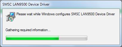
Figure 30: SMSC LAN9500 device driver installation.
Another ICS driver installer dialog box will now appear, similar to the first one.
14. Install ICS Port Drivers: Click Next > to begin installing the ICS port drivers.
At this point you may receive a prompt from Windows like the one shown in Figure 31. Please click Install to authorize driver installation.
Figure 31: Windows Security Dialog Box.
Once installation begins, it will take only a few moments, and when completed, a message will appear like the one in Figure 32.
15. Complete Port Driver Installation: Click Finish to exit this part of the install.
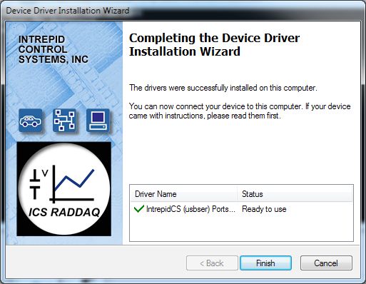
Figure 32: Port Driver Installation Complete.
You will now see a window similar to Figure 33, indicating that the setup process is complete.
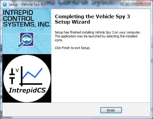
Figure 33: Vehicle Spy 3 Setup Complete.
16. Exit the Setup Wizard: Click Finish >.
Congratulations, you’re done!
5.2. Driver and API Support File Installation and Setup
If you plan to use the neoVI RED 2 without Vehicle Spy 3, you will need to install drivers and support files to allow the hardware to be accessed via its API. Please follow the steps below.
All of these files are installed automatically with Vehicle Spy 3, so if you followed the instructions in Section 4.1, you can skip the directions here.
1. Load the Software and Documentation Disc: Insert the disc that came with your neoVI RED 2 into the optical drive of your computer. A few seconds later, the ICS software installation menu should automatically appear on your computer screen, as shown in Figure 34.
Note
Note: On some computers this window may not appear automatically. If this occurs, start Windows Explorer, navigate to the disc’s letter under Computer, and then double-click the file icsAutoPlay.exe to open the menu.
Figure 34: neoVI RED 2 Software Install Dialog Box.
2. Start Support File Installation: Click RP1210 J2534 Intrepid API Install.
3. Select Language: Select your preferred language, and then click OK to proceed. (We will assume that English has been used.)
The setup wizard for the ICS API and driver kit will now start, displaying a welcome screen as shown in Figure 35. (The version number you see may be different from the one shown here.)

Figure 35: API and Driver Setup Wizard Welcome Screen.
4. Start API and Driver Setup Wizard: Click Next > to start the setup wizard.
5. Review and Accept License Agreement: Review the license agreement, and assuming its terms are acceptable, select I accept the agreement, then click (Figure 36).
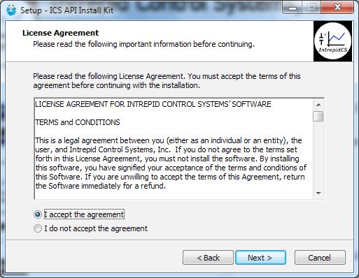
Figure 36: API and Driver File License Agreement.
6. Select Installation Type: We are doing a new installation so simply click Next> to continue.
7. Select Destination Location: Choose where you want to install Vehicle Spy 3 (Figure 37). We normally recommend keeping the default location. Click Next >.
Figure 37: Choosing the API Kit Destination Location
You have now provided all of the information the wizard needs, and it will display a summary as shown in Figure 38.
Figure 38: API Installation Options Review
8. Review Installation Options and Begin Installation: Ensure that the options you have chosen are correct, and then click Install.
The wizard will now begin installing Vehicle Spy 3. A window will appear showing you the progress of the installation (Figure 39).
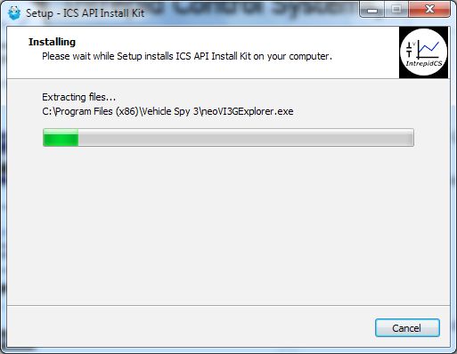
Figure 39: Installing API and Drivers.
After completing the basic setup, the wizard will automatically install various drivers required by the neoVI RED 2. The first install will be done by the VCP Driver Installer.
9. Install VCP Drivers: Click Next > to begin installing the first set of drivers. When completed, a message will appear like the one in Figure 40. Click Finish.
Figure 40: VCP Driver Installation Complete.
Next, support files for Microsoft Visual C++ 2010 and 2005 will be automatically installed, if they are not already on the computer. You may briefly see a dialog box like the one in Figure 41. If a prompt appears saying the files are already installed, hit OK to continue
Figure 41: Installing Support Files for Microsoft Visual C++ 2005
Another ICS driver installer dialog box will appear now.
10. Install ICS Port Drivers: Click Next to begin installing the ICS port drivers.
If you see a Windows dialog like the one in Figure 42, click Install to authorize installation.
Figure 42: Windows Security Dialog Box
Once installation begins, it will take only a few seconds, and when completed, a message will appear like the one in Figure 43.
11. Complete Port Driver Installation: Click Finish to exit this part of the install.
Figure 43: Port Driver Installation Complete.
You will now see a dialog box like the one shown in Figure 44, indicating that the setup process is complete.
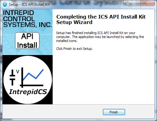
Figure 44: Vehicle Spy 3 Setup Complete.
12. Exit the Setup Wizard: Click Finish.
Congratulations, you’re done!
5.3. Hardware Hookup Diagrams
Hookup diagrams show you at a glance how to physically connect your neoVI RED 2 to vehicle networks and your PC. Below you will find first a hookup diagram for using the RED 2 without an OBD cable, and then five additional ones showing the connections for each of the OBD cable options discussed in Section 3.5.
Four of the OBD cables–the neoVI-OBD-1, neoVI-OBD-MULTI, neoVI-OBD-MULTI Right Angle, and neoVI FIRE/RED J1939–are connected to the DB-25 of the Fire 2 Ethernet Cable Adapter and then attach to an OBD port on a vehicle or network test bench. The fifth, the RED 2 OBD Cable with DoIP Support, replaces the RED 2 Ethernet Cable Adapter.
Basic Hardware Hookup Diagram
Figure 45 shows the basic hardware configuration of the neoVI RED 2, with the USB cable connecting the device to the PC, and the RED 2 Ethernet Cable Adapter linking it to vehicle networks.
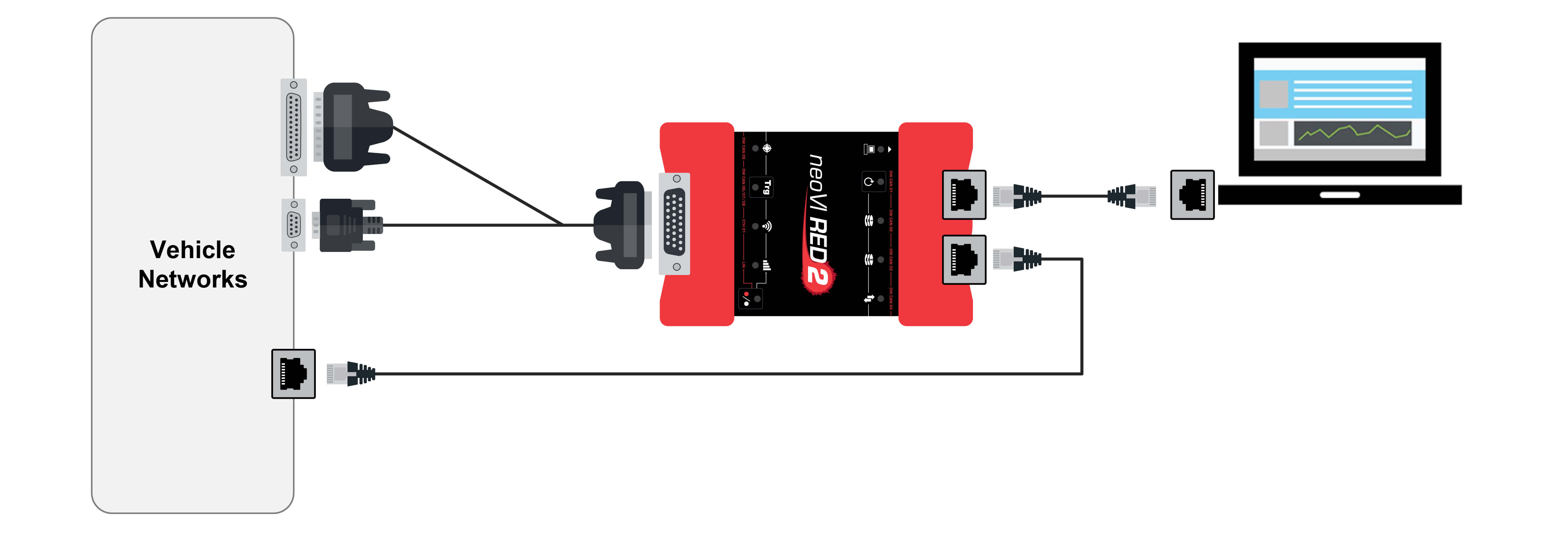
Figure 45: Basic RED 2 Hardware Hookup Diagram. This diagram shows basic connections with no OBD cable.
OBD Hardware Hookup Diagram - neoVI-OBD-1 Cable
In Figure 46 you can see the basic hardware setup from Figure 46 but with the addition of the neoVI-OBD-1 cable.
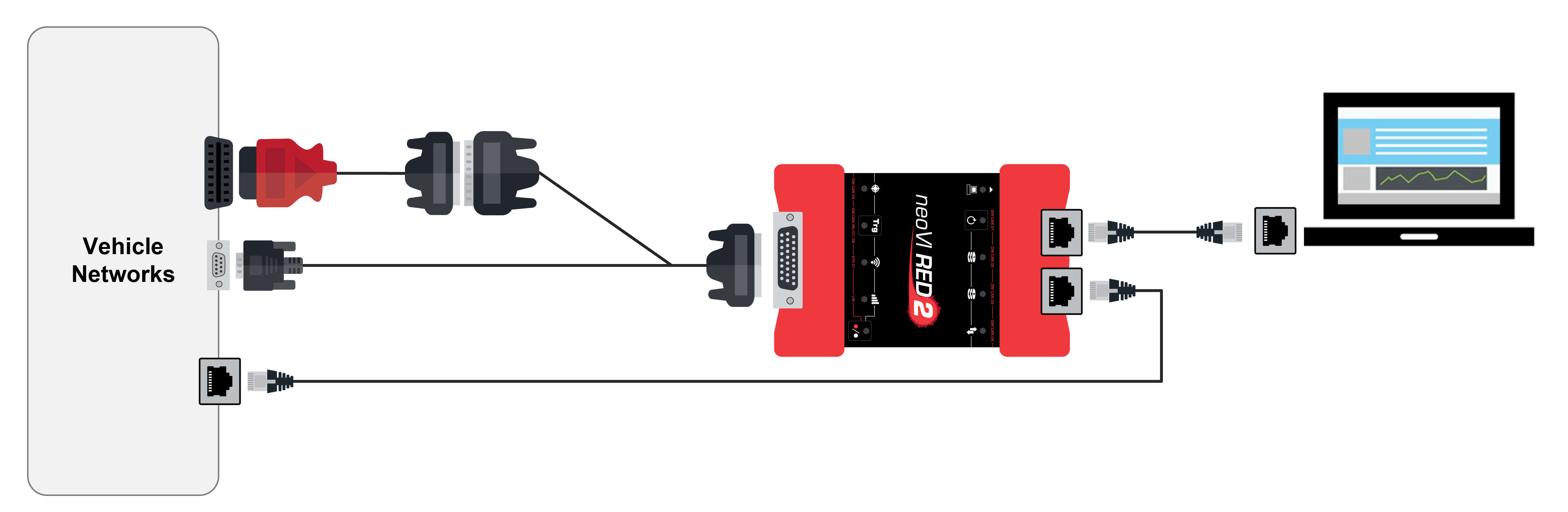
Figure 46: RED 2 Hardware Hookup Diagram with neoVI-OBD-1 Cable.
OBD Hardware Hookup Diagram - neoVI-OBD-MULTI Cable
Figure 47 shows the hardware setup using the neoVI-OBD-MULTI cable.
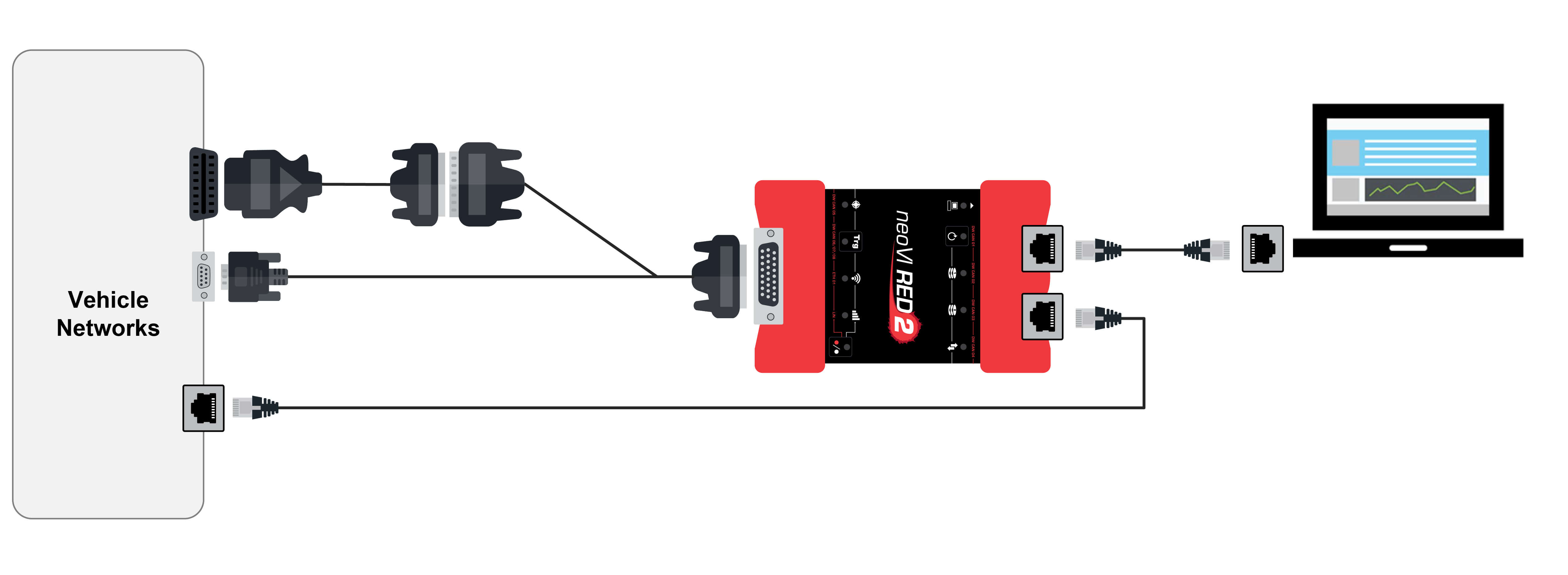
Figure 47: RED 2 Hardware Hookup Diagram with neoVI-OBD-MULTI Cable.
OBD Hardware Hookup Diagram - neoVI-OBD-MULTI Right Angle Cable
The hardware setup for the neoVI-OBD-MULTI Right Angle cable is the same as that of the neoVI-OBD-MULTI, except the OBD connector is at a right angle to the cable for use where this is convenient (Figure 48).
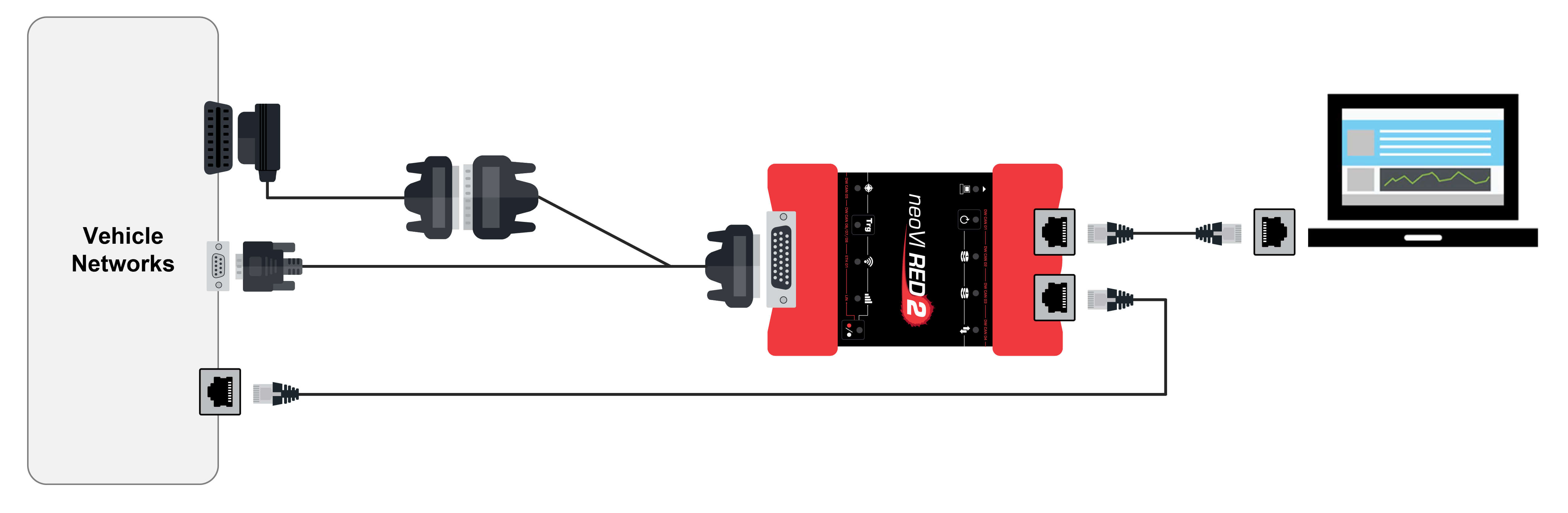
Figure 48: RED 2 Hardware Hookup Diagram with neoVI-OBD-MULTI Right Angle Cable.
OBD Hardware Hookup Diagram - neoVI RED J1939 Cable
Figure 49 shows the setup when using the neoVI RED J1939 cable for OBD.
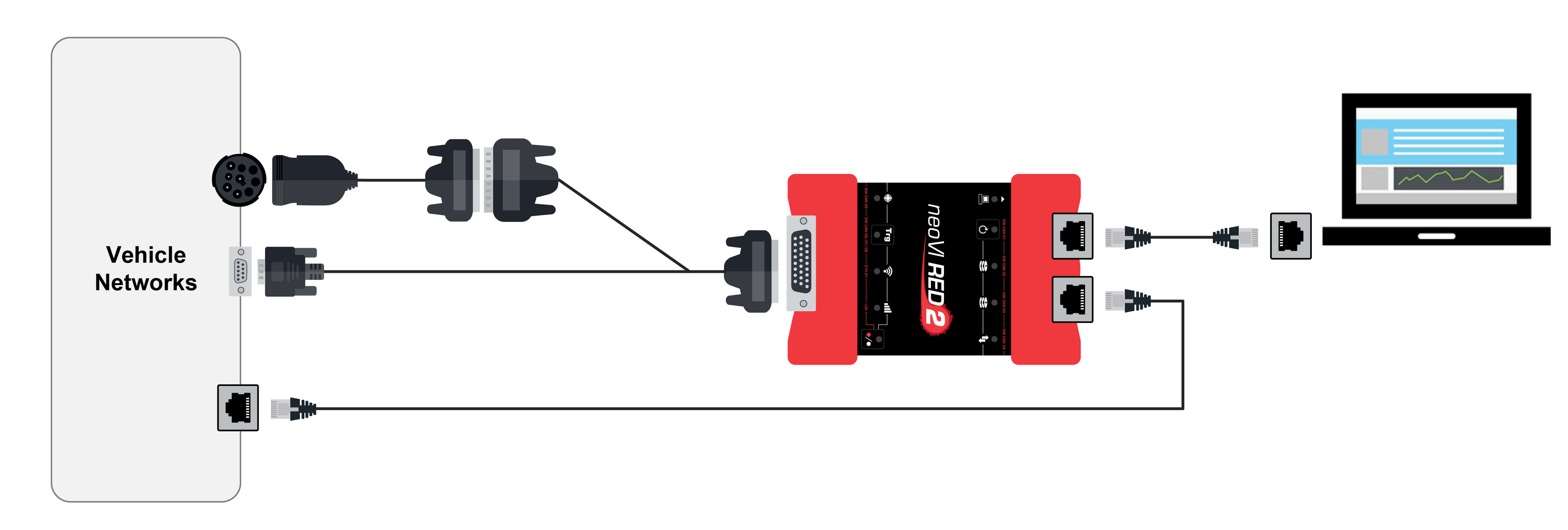
Figure 49: RED 2 Hardware Hookup Diagram with neoVI RED J1939 Cable
OBD Hardware Hookup Diagram - RED 2 OBD Cable with DoIP Support
The special RED 2 OBD Cable with DoIP Support replaces the Fire 2 Ethernet Cable Adapter as shown in Figure 50.
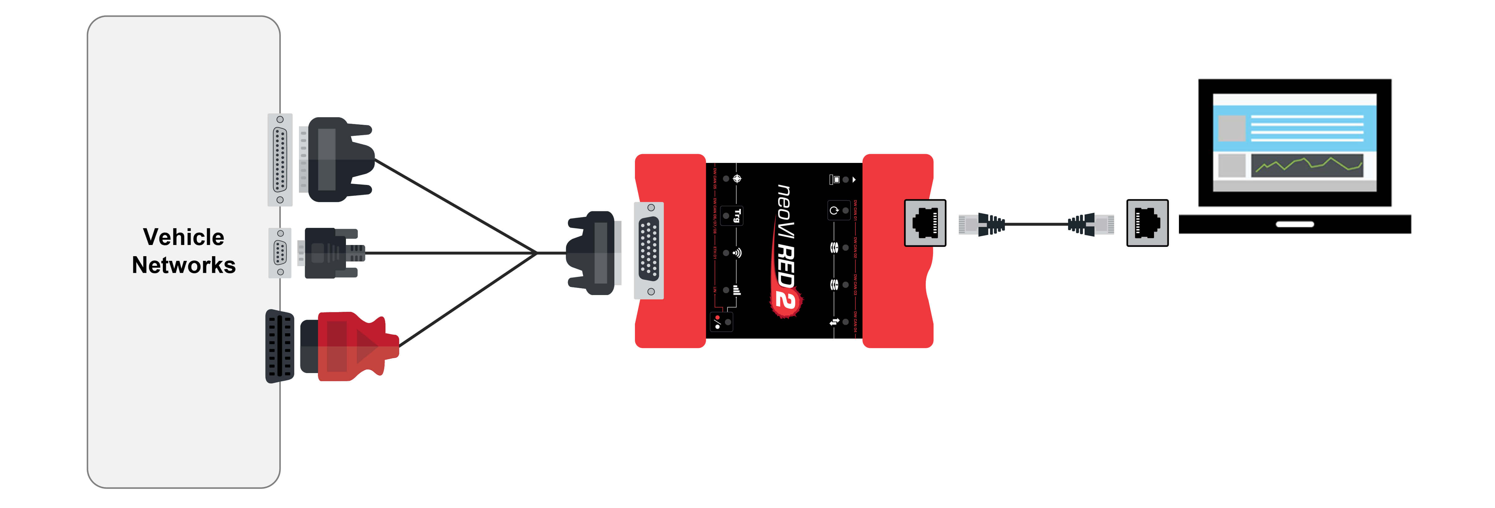
Figure 50: RED 2 Hardware Hookup Diagram with FIRE 2 OBD Cable with DoIP Support
5.4. Vehicle Network and Power Connections
Two connectors on the RED 2 are used to attach it to vehicle networks. The HD-26 connector on the left side of the device provides primary power input to the neoVI RED 2 and also carries most of the network channels. This is also where your OBD cable is attached, either directly or indirectly.
The connection steps are listed in a specific order chosen to make the process intuitive, and to prioritize the power connection so you can verify quickly that the RED 2 is operational. However, the steps can be performed in any order you find convenient
HD-26 and OBD Cable Connections to RED 2
The connections made here will depend on which OBD cable, if any, you are using with the RED 2.
If you are using no OBD cable, or any OBD cable other than the RED 2 OBD Cable with DoIP Support:
1. Attach FIRE 2 Ethernet Cable Adapter to HD-26 Connector: Attach the HD-26 female connector on the network interface cable to the HD-26 male connector on the neoVI RED 2. Tighten the thumbscrews so the cable remains securely attached (Figure 51)
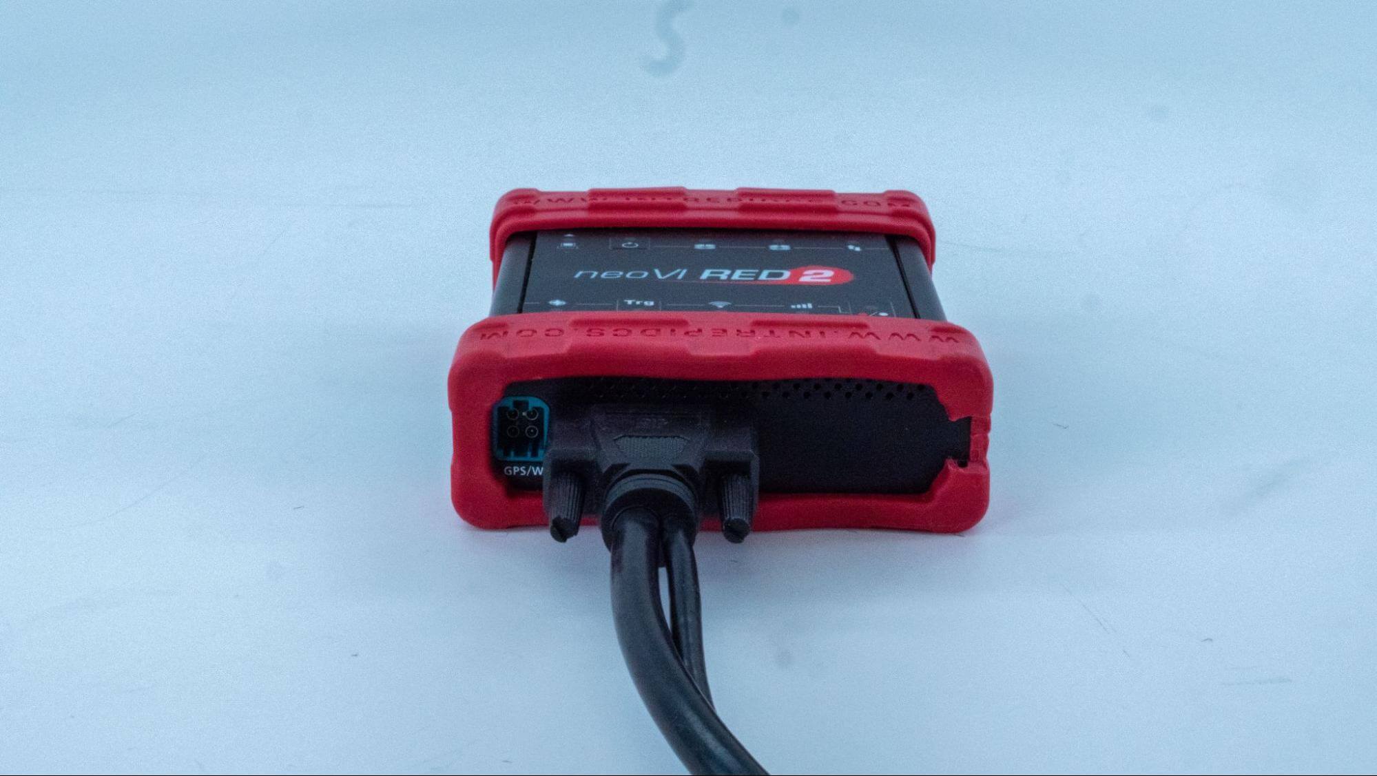
Figure 51: Connecting the HD-26 Cable Connector to the neoVI RED 2.
2. Attach OBD Cable to DB-25 Connector on FIRE 2 Ethernet Cable Adapter (OBD Use Only): Connect the female DB-25 connector of your neoVI-OBD-1, neoVI-OBDMULTI, neoVI-OBD-MULTI Right Angle or neoVI RED J1939 cable to the male DB-25 of the FIRE 2 Ethernet Cable Adapter (Figure 52).
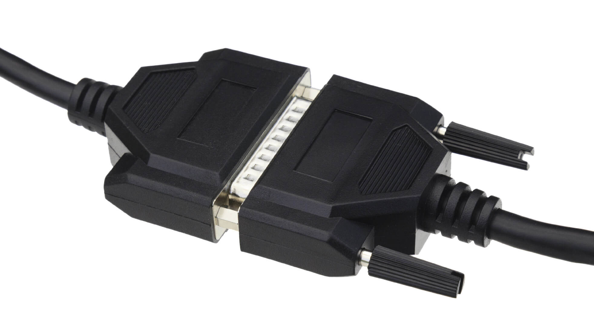
Figure 52: Attaching the DB-25 Connector of an OBD Cable to the DB-25 on the FIRE 2 Ethernet Cable Adapter.
3. Attach DB-25, DB-9, RJ-45, J1939 and/or OBD-II Connectors to Vehicle Network: Attach the connectors from the FIRE 2 Ethernet Cable Adapter and your OBD cable (if using) to their mating halves on your network, then secure them in place.
As soon as you connect the device supplying power to the cable attached to the neoVI RED 2, the device should boot up. You will recognize this by green LEDs beginning to flash in a quick and regular pattern on both the side of the device next to the HD-26 connection, and in the upper left corner of the top membrane interface. If the LEDs do not start flashing, please see Chapter 9 for assistance.
The neoVI RED 2 should now be fully connected to your vehicle or bench network.
5.5. PC Connection
Now we will connect the RED 2 to the PC. This can be done either directly to a ethernet cable or 2.0 (or higher) port using the adapter provided by Intrepid on the computer, or indirectly through a USB hub or Ethernet switch.
If you are using the neoVI RED 2 with USB adapter, then the USB standard maximum of 500 mA through its USB connection. All computers should be able to supply this amount of current, however, unpowered USB hubs may not be able to do so, especially if they have multiple devices connected to them. If you experience difficulties with the RED 2 when using an unpowered hub port, but the device works when connected directly to a PC USB slot, you probably need to use the PC slot or a powered hub.
1. Attach Ethernet Cable to RED 2: Insert the ethernet cable into the matching receptacle on the right side of the RED 2 (Figure 53).
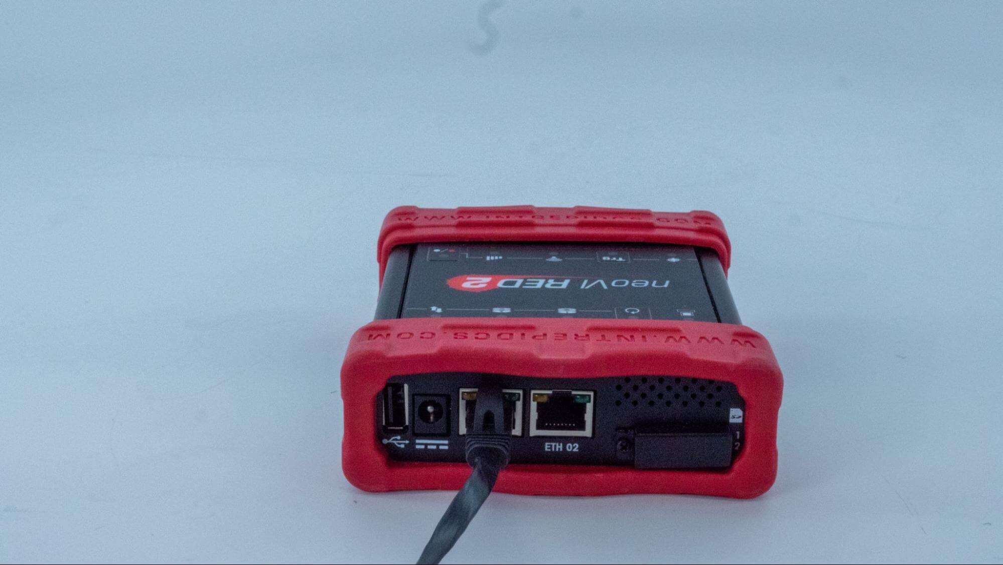
Figure 53: Connecting the Ethernet Cable to the neoVI RED 2.
2. Attach Ethernet Connector to PC or USB Hub if you are using the provided Ethernet to USB adapter: Attach the standard rectangular USB connector to your PC or USB hub.
Upon making the USB connection, you may notice messages within Windows informing you that drivers are being installed. These were in fact actually installed when you ran Vehicle Spy or the API installation utility, but are configured the first time the device is attached. If you see error messages associated with drivers at this point, please contact Intrepid for assistance.