9. Reference: Connector Pinouts and Cable Signal Mappings
This section contains complete pinouts for the connectors on the neoVI RED 2, as well as those on the network interface cables used to attach to it. For your convenience, tables are also provided that show the mappings of signals between pin numbers on the connectors of each network cable.
Note that the USB cable is industry standard and not covered here.
9.1. neoVI RED 2 Connector Pinouts
We’ll start with the pinouts for the connectors on the neoVI RED 2 itself.
HD-26 Connector Pinout
A list of pin assignments for the HD-26 connector can be found in Table 4, with pin numbering for the connector illustrated in Figure 86.
| Pin # | Name | Description |
|---|---|---|
| 1 | MISC 1 | Miscellaneous 1 (0–3.3V) DI/O |
| 2 | DW CAN 4 L | Dual Wire CAN 4 Low |
| 3 | DW CAN 5 L | Dual Wire CAN 5 Low |
| 4 | DW CAN 1 L | Dual Wire CAN 1 Low |
| 5 | DW CAN 8 L | Dual Wire CAN 8 Low |
| 6 | DW CAN 2 L | Dual Wire CAN 2 Low |
| 7 | DW CAN 3 L | Dual Wire CAN 3 Low |
| 8 | DW CAN 6 L | Dual Wire CAN 6 Low |
| 9 | MISC 2 | Miscellaneous 2 Enhanced miscellaneous I/O (analog or digital with PWM and 0–40V support) AI/O + DI/O |
| 10 | GND | Ground |
| 11 | MISC 3 | Miscellaneous 3 (0–3.3V) DI/O |
| 12 | DW CAN 4 H | Dual Wire CAN 4 High |
| 13 | DW CAN 5 H | Dual Wire CAN 5 High |
| 14 | DW CAN 1 H | Dual Wire CAN 1 High |
| 15 | DW CAN 8 H | Dual Wire CAN 8 High |
| 16 | DW CAN 2 H | Dual Wire CAN 2 High |
| 17 | DW CAN 3 H | Dual Wire CAN 3 High |
| 18 | DW CAN 6 H | Dual Wire CAN 6 High |
| 19 | VBAT | DC Input Power |
| 20 | MISC 4 | Miscellaneous 4 (0–3.3V) DI/O |
| 21 | DW CAN 7 L | Dual Wire CAN 7 Low |
| 22 | LIN 01 / ISO K 01 | LIN Channel 1 |
| 23 | LIN 02 | LIN Channel 2 |
| 24 | EXT WAKE | External Wake |
| 25 | ETH 01 ACTIVATE | Ethernet Activation Line |
| 26 | DW CAN 7 H | Dual Wire CAN 7 High |
Table 4: neoVI RED 2 HD-26 Connector Pinout.
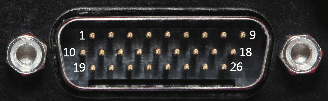
Figure 86: neoVI RED 2 HD-26 Connector Pin Numbering
9.2. DB26-1 CABLE ADAPTER (DB26HD-F TO DB-25M + DB-9M)
Converts the HD-26F connector on products with a DB26-1 connector to 1x DB-25M and 1x DB-9 connector.
This cable is required to adapter for all this cable listed below in order to use it with your neoVI RED 2
- GM Global A T-Harness [GA-CGM3] https://store.intrepidcs.com/product/GA-CGM3
- Deutsch 9-pin (J1939 Type 1) Cable [J1939-FIRE-CABLE] https://store.intrepidcs.com/product/J1939-FIRE-CABLE
- OBD Multi (Right Angle Connector) [NEOVI-OBD-MULTI-RIGHT] https://store.intrepidcs.com/product/NEOVI-OBD-MULTI-RIGHT
- OBD Multi Cable (Most OEMs) [NEOVI-OBD-MULTI] https://store.intrepidcs.com/product/NEOVI-OBD-MULTI
- GM Legacy Cable (Global A) [NEOVI-OBD-1] https://store.intrepidcs.com/product/NEOVI-OBD-1
Pinout
Table 5 lists the pins of the DHD-26F Pin, DB-25M Pin, DB-9M Pin
| Signal | HD-26F Pin # | DB-25M Pin # | DB-9M Pin # |
| MISC 1 | 1 | – | 6 |
| DW CAN 4 L | 2 | 23 | – |
| DWCAN 5 L | 3 | 22 | – |
| DW CAN 1 L | 4 | 15 | – |
| DW CAN 8 L | 5 | 6 | – |
| DW CAN 2 L | 6 | 17 | – |
| DW CAN 3 L | 7 | 20 | – |
| DW CAN 6 L | 8 | 4 | – |
| MISC 2 | 9 | – | 7 |
| GND | 10 | 13 | 5 |
| MISC 3 | 11 | – | 8 |
| DW CAN 4 H | 12 | 18 | – |
| DW CAN 5 H | 13 | 21 | – |
| DW CAN 1 H | 14 | 14 | – |
| DW CAN 8 H | 15 | 5 | – |
| DW CAN 2 H | 16 | 16 | – |
| DW CAN 3 H | 17 | 19 | – |
| DW CAN 6 H | 18 | 3 | – |
| V+ | 19 | 25 | – |
| MISC 4 | 20 | – | 9 |
| DW CAN 7 L | 21 | 7 | – |
| LIN 1 | 22 | 8 | 1 |
| LIN 2 | 23 | – | 2 |
| EXT WAKE | 24 | – | 3 |
| ETH ACTIVATE (DOIP) | 25 | – | 4 |
| DW CAN 7 H | 26 | 1 | – |
9.3. BREAKOUT CABLE (DB-26HD FEMALE TO 11X DB-9M + 2X BANANA PLUGS)
This cable breaks out the DB-26HD Female connector on the DB26 connector of the neoVI Red 2 and the DB26-1 connector on the neoVI Fire 3 to separate DB-9M connectors for 8x CAN, and 2x LIN;and 1x DB9 for all remaining MISC IO, External Wake and DoIP Activation.Two banana plugs are provided to connect power to the neoVI.
Connector Pinouts and Signal Mapping
| Pin # (HD26F) | 04 | 14 | 05 | 15 | 06 | 16 | 7 | 17 | 02 | 12 | 03 | 13 | 08 | 18 | 21 | 26 |
| Signal (DB 9M) | HSCAN1 | HSCAN8 | HSCAN2 | HSCAN3 | HSCAN4 | HSCAN5 | HSCAN6 | HSCAN7 | ||||||||
| CAN Low | Pin 2 | |||||||||||||||
| CAN High | 7 | |||||||||||||||
| GND/PWR | 3 | 3 | 3 | 3 | 3 | 3 | 3 | 3 | ||||||||
LIN
| Pin # (HD26F) | 22 | 23 |
| Signal (DB 9M) | LIN1 | LIN2 |
| 2 | 2 | |
| GND/PWR | 3 | 3 |
DB9 (MISC)
| Pin # DB26 | 1 | 9 | 11 | 20 | 24 | 25 |
| Pin # DB9 | 8 | 9 | 6 | 7 | ||
| Signal | MISC 1 | MISC 2 | MISC 3 | MISC 4 |
Banana Jacks
| Pin # (HD26F) | 19 | 10 |
| Plugs | PWR+ | GND– |
9.4. DB26-1 DoIP Cable (Red2, Fire3) [DB26-1-DOIP-CABLE]
Connects the DB26-1 connector on the neoVI Fire 3 / Red 2 Series to an OBD-II (J1962) connector for DoIP. RJ-45 on this cable is connected to ETH01 port via a separate CAT6 cable for DoIP functionality.
9.5. GM Global A T-Harness [GA-CGM3]
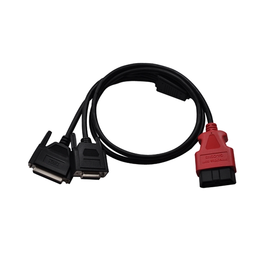
Figure 87: neoVI RED 2 GM Global A T-Harness adapter cable
This adapter cable allows you to connect the neoVI Fire or the neoVI Fire 2 to a Global A vehicle or bench with CGM.
Connector Pinouts and Signal Mapping coming soon
9.6. Deutsch 9-pin (J1939 Type 1) Cable [J1939-FIRE-CABLE]
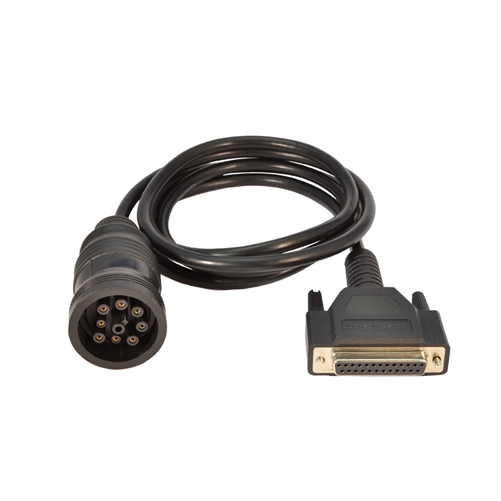
Figure 88: neoVI RED 2 Deutsch 9-pin (J1939 Type 1) cable
This cable converts the female DB-25 on neoVI hardware devices or other cables to a Deutsch 9-pin (J1939) cable for use with commercial vehicles. It uses the standard J1939 pinout, including dual CAN channels.
NOTE: This cable does not support the neoVI BLUE with dual CAN, but may be used with it for single CAN J1939.
Connector Pinouts and Signal Mapping
| Deutsch Signal | Deutsch Pin # | DB-25F Pin # | DB-25F Signal |
| Ground (–) | 1/A | 13 | GND |
| Battery (+) | 2/B | 25 | VBATT |
| CAN High (+) | 3/C | 14 | HS CAN H |
| CAN Low (–) | 4/D | 15 | HS CAN L |
| CAN Shield | 5/E | N/C | N/C |
| J1708 (+) | 6/F | N/C | N/C |
| J1708 (–) | 7/G | N/C | N/C |
| CAN2 High (+) | 8/H | 5 | MS CAN H |
| CAN2 Low (–) | 9/J | 6 | MS CAN L |
9.7. OBD Multi (Right Angle Connector) [NEOVI-OBD-MULTI-RIGHT]
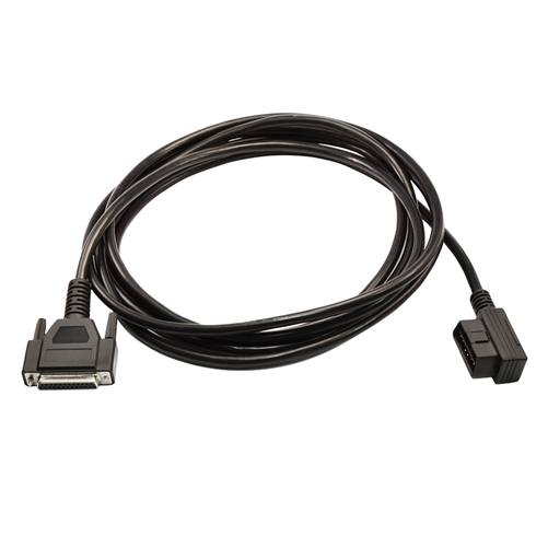
Figure 89: neoVI RED 2 OBD Multi (Right Angle Connector)
This cable converts the DB-25M connector on many Intrepid hardware devices to a right-angled OBD-II connector, for applications where this is required. It differs from the NEOVI-OBD-1 in that its pinout matches the needs of most newer vehicles using multiple DW CAN channels.
Note that this cable is the same as the NEOVI-OBD-MULTI except for the shape of the OBD-II connector.
OBD-II Connector Pinout (Vehicle Side View)
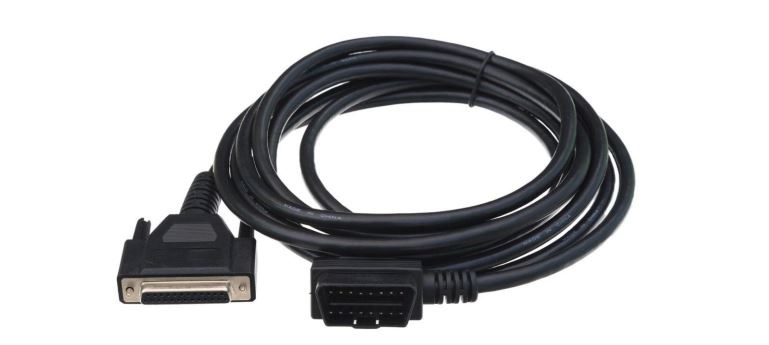
Figure 90: neoVI RED 2 OBD Multi Side View
Connector Pinouts and Signal Mapping
| OBD-II Pin # | OBD-II Signal | DB-25F Signal | DB-25F Pin # |
| 1 | Discretionary* | HS CAN 3 H | 19 |
| 2 | SAE J1850 + | N/C | N/C |
| 3 | Discretionary* | MS CAN H | 5 |
| 4 | Chassis Ground | N/C | N/C |
| 5 | Signal Ground | PWR GND | 13 |
| 6 | CAN H (ISO16765-4 and SAE-J2284) | HS CAN 1 H | 14 |
| 7 | ISO9141/K | ISO9141/K/LIN1 | 8 |
| 8 | Discretionary* | N/C | N/C |
| 9 | Discretionary* | HS CAN 3 L | 20 |
| 10 | SAE J1850– | N/C | N/C |
| 11 | Discretionary* | MS CAN L | 6 |
| 12 | Discretionary* | HS CAN 2 H | 16 |
| 13 | Discretionary* | HS CAN 2 L | 17 |
| 14 | CAN L (ISO16765-4 and SAE-J2284) | HS CAN 1 L | 15 |
| 15 | L line of ISO9141-2 | ISO L | 7 |
| 16 | Unswitched Vehicle Battery Positive | VBATT | 25 |
Note: - The table above shows standard signals for the OBD-II connector; this includes J1850, which is not supported by current Intrepid hardware devices.
9.8. OBD Multi Cable (Most OEMs) [NEOVI-OBD-MULTI]

Figure 91: neoVI RED 2 OBD Multi Cable
This cable converts the DB-25M connector on many Intrepid hardware devices to a standard OBD-II connector. It differs from the NEOVI-OBD-1 in that its pinout matches the needs of most newer vehicles using multiple DW CAN channels.
OBD-II Connector Pinout (Vehicle Side View)
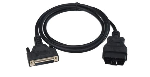
Figure 92: neoVI RED 2 OBD Multi Side View
Connector Pinouts and Signal Mapping
| OBD-II Pin # | OBD-II Signal | DB-25F Signal | DB-25F Pin # |
| 1 | Discretionary* | HS CAN 3 H | 19 |
| 2 | SAE J1850 + | N/C | N/C |
| 3 | Discretionary* | MS CAN H | 5 |
| 4 | Chassis Ground | N/C | N/C |
| 5 | Signal Ground | PWR GND | 13 |
| 6 | CAN H (ISO16765-4 and SAE-J2284) | HS CAN 1 H | 14 |
| 7 | ISO9141/K | ISO9141/K/LIN1 | 8 |
| 8 | Discretionary* | N/C | N/C |
| 9 | Discretionary* | HS CAN 3 L | 20 |
| 10 | SAE J1850– | N/C | N/C |
| 11 | Discretionary* | MS CAN L | 6 |
| 12 | Discretionary* | HS CAN 2 H | 16 |
| 13 | Discretionary* | HS CAN 2 L | 17 |
| 14 | CAN L (ISO16765-4 and SAE-J2284) | HS CAN 1 L | 15 |
| 15 | L line of ISO9141-2 | ISO L | 7 |
| 16 | Unswitched Vehicle Battery Positive | VBATT | 25 |
Note: - The table above shows standard signals for the OBD-II connector; this includes J1850, which is not supported by current Intrepid hardware devices.
9.9. GM Legacy Cable (Global A) [NEOVI-OBD-1]
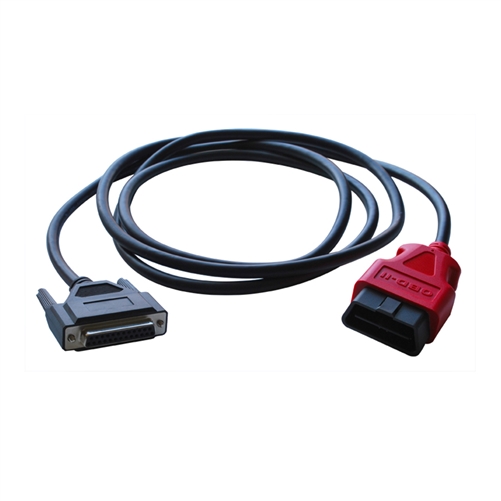
Figure 93: neoVI RED 2 GM Legacy Cable (Global A) [NEOVI-OBD-1] Cable
This cable adapts the DB-25M connector on many Intrepid hardware devices to a standard OBD-II connector. It has a pinout different from that of the NEOVI-OBD-MULTI, well-suited to GM vehicles.
OBD-II Connector Pinout (Vehicle Side View)
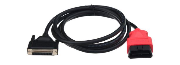
Figure 94: neoVI RED 2 GM Legacy Cable (Global A) Side View
Connector Pinouts and Signal Mapping
| OBD-II Pin # | OBD-II Signal | DB-25F Signal | DB-25F Pin # |
| 1 | Discretionary* (GMLAN SW CAN) | SW CAN | 1 |
| 2 | SAE J1850 + | J1850 VPW | 2 |
| 3 | Discretionary* (GMLAN MS CAN H) | MS CAN H | 5 |
| 4 | Chassis Ground | N/C | N/C |
| 5 | Signal Ground | PWR GND | 13 |
| 6 | Discretionary* (GMLAN HS CAN H) | HS CAN 1 H | 14 |
| 7 | ISO9141/K | ISO9141/K/LIN1 | 8 |
| 8 | Discretionary* | N/C | N/C |
| 9 | Discretionary* (GM ALDL) | HS CAN 3 H | 19 |
| 10 | SAE J1850 - | HS CAN 3 L | 20 |
| 11 | Discretionary* (GMLAN MS CAN L) | MS CAN L | 6 |
| 12 | Discretionary* | HS CAN 2 H | 16 |
| 13 | Discretionary* | HS CAN 2 L | 17 |
| 14 | Discretionary* (GMLAN HS CAN L) | HS CAN 1 L | 15 |
| 15 | L line of ISO 9141-2 | ISO L | 7 |
| 16 | Unswitched Vehicle Battery Positive | VBATT | 25 |
Note: - The table above shows standard signals for the OBD-II connector; this includes J1850, which is not supported by current Intrepid hardware devices.